
Large-Scale Recovery Boiler Soot Blowing System: 84 Long Retractable Soot Blowers for 1200 tDS/d Service
A 1200 tDS/d recovery boiler cleaning system using 84 SW-SLRM long retractable soot blowers with coordinated piping, controls and DCS integration.
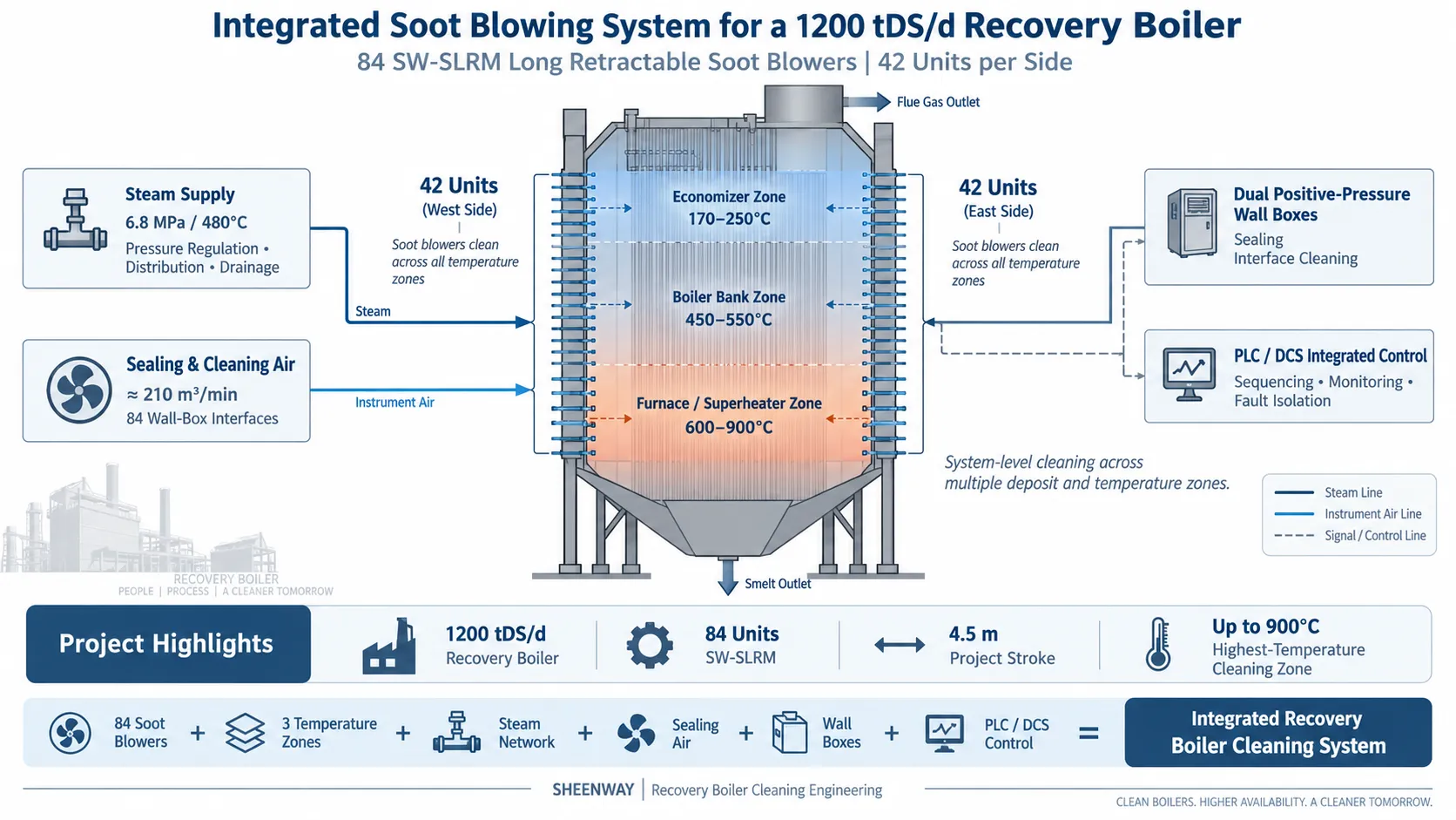
A large recovery boiler requires more than individual soot blowers. It requires a coordinated cleaning system capable of maintaining reliable operation across multiple temperature zones while handling the deposit characteristics associated with black-liquor combustion.
In this project, SHEENWAY engineered and supplied a large-scale steam soot blowing system for a 1200 tDS/d recovery boiler at a pulp manufacturing facility in southwest China.
The system incorporated 84 SW-SLRM Long Retractable Soot Blowers, symmetrically arranged on both sides of the boiler, together with steam piping, pressure regulation, drainage, positive-pressure sealing, sealing and cleaning air, electrical systems, PLC control and DCS integration.
With 84 soot blowers operating as part of one coordinated boiler-cleaning system, the engineering challenge extended well beyond the individual machine.
Project Overview
The recovery boiler was designed for a solids processing capacity of approximately 1200 tDS/d, with a design steam generation capacity of approximately 145 t/h.
The main steam conditions were approximately:
6.8 MPa / 480°C
A total of 84 SW-SLRM Long Retractable Soot Blowers were arranged across the boiler, with:
42 units on each side.
The project-specific soot blower stroke was approximately 4.5 meters, with an effective cleaning radius of approximately 2 meters and 360° blowing coverage.
The system was designed to clean recovery-boiler heating surfaces including the high-temperature furnace/superheater region, boiler-bank sections and economizer sections.
Rather than designing each soot blower as an isolated machine, the project considered the 84 units, steam system, sealing system, control architecture and boiler interfaces as one integrated cleaning system.
Black-Liquor Firing Conditions
The boiler was designed to fire concentrated black liquor.
Project design data specified an entering black-liquor solids concentration of approximately 68%, at a temperature of approximately 120°C, with a higher heating value of approximately 13.4 MJ/kgDS.
The dry-solids elemental analysis also indicated a substantial alkali content, including approximately 20.2% sodium and 2.4% potassium.
For a recovery boiler, these fuel characteristics make deposit management an integral part of boiler operation.
The soot blowing system therefore had to provide dependable online cleaning under conditions very different from those encountered in many conventional industrial boilers.
The engineering objective was not simply to generate a strong steam jet, but to maintain controlled and repeatable cleaning across a large boiler while protecting the heating surfaces and maintaining reliable soot blower movement.
Multiple Temperature Zones from 170°C to 900°C
One of the defining characteristics of this project was the wide range of operating temperatures across the boiler.
The design flue-gas temperatures were approximately:
600–900°C in the furnace/superheater region,
450–550°C in the boiler-bank region, and
170–250°C in the economizer region.
This meant that all 84 soot blowers could not simply be treated as identical installations from an engineering perspective.
The actual soot blowing parameters had to consider local flue-gas temperature, deposit characteristics, heating-surface arrangement and available steam conditions.
This principle is also reflected in SHEENWAY's current SW-SLRM engineering standard: stroke, travel speed, rotational speed, nozzle arrangement, blowing pressure and flow are determined according to the boiler's actual operating conditions rather than by applying one universal parameter set.
84 SW-SLRM Long Retractable Soot Blowers
The project utilized SW-SLRM Long Retractable Soot Blowers with an approximately 4.5 m project stroke.
During operation, the lance advances into the boiler while rotating, allowing the steam jets to clean the required heating-surface area. After the blowing cycle, the lance retracts from the boiler.
The project required a rigid dual-track, dual-rack box-beam structure, rather than a simpler single-rail I-beam arrangement.
For an 84-unit system operating repeatedly throughout the boiler, mechanical consistency was an important design consideration.
The project also specified an effective cleaning radius of approximately 2 m and a steam consumption of no more than approximately 120 kg/min per soot blower under the specified operating conditions.
T91 Lance Tubes for High-Temperature Service
The soot blower lance tubes were specified in T91 material.
This was particularly significant because part of the soot blowing system operated in flue-gas zones reaching design temperatures of up to approximately 900°C.
Material selection for a recovery-boiler lance must take into account more than nominal gas temperature.
Long-term thermal exposure, repeated insertion and retraction, steam conditions, mechanical loading and the deposit environment all influence the requirements placed on the lance tube.
The project therefore combined high-temperature material selection with a retractable operating principle that removes the lance from the boiler after each cleaning cycle.
Dual Positive-Pressure Wall Boxes
The interface between each soot blower and the recovery boiler was another important part of the system design.
The project specified dual positive-pressure wall boxes.
One sealing path uses air pressure to help prevent furnace gas from escaping through the boiler penetration and entering the soot blower assembly.
The second path provides a cleaning function during soot blower operation, helping to limit deposit accumulation around the lance as it moves through the wall penetration.
This provides two complementary functions:
sealing the boiler penetration and maintaining a cleaner lance-interface environment.
For a recovery boiler with 84 penetrations, wall-box performance becomes a system-level reliability issue rather than a minor accessory detail.
Large-Scale Sealing and Cleaning Air System
The project therefore incorporated a dedicated sealing and cleaning air network for the soot blowers.
The specified furnace positive pressure was approximately 5 kPa, and the air system was designed to supply all 84 soot blower sealing points.
The total specified sealing-air flow was approximately 210 m³/min, with individual soot blower interfaces sized at approximately DN40.
The objective was to maintain positive-pressure protection around the soot blower penetrations under both operating and standby conditions.
This helps reduce flue-gas migration into the soot blower, supports wall-box sealing and assists in maintaining the cleanliness of the lance-interface area.
For an 84-unit installation, air distribution, piping layout and pressure stability become critical parts of the overall soot blowing system engineering.
Steam Supply, Pressure Regulation and Drainage
The available steam source for the system was approximately:
6.8 MPa / 480°C
The soot blowing system therefore included engineering for steam pressure reduction and distribution before steam entered the individual soot blowers.
Project-specific blowing pressure at the soot blower valve outlet was designed within the required operating range, while each soot blower incorporated flow-control capability.
The complete steam system also considered:
steam pressure reduction, drainage, flow capacity, pressure loss, thermal expansion, piping support, instrumentation and maintenance access.
The project required drainage piping to avoid condensate accumulation and to allow condensate to flow reliably toward the designated collection system.
This is particularly important in a large soot blowing network, because inconsistent steam conditions can produce inconsistent cleaning performance across different parts of the boiler.
Protecting Boiler Tubes from Repeated Jet Impact
Effective soot blowing does not mean directing the strongest possible jet at the same location during every cycle.
The project therefore incorporated a helical phase-change mechanism to change the relative cleaning trajectory between successive soot blowing cycles.
This helps reduce repeated jet impact on exactly the same tube positions.
The engineering objective is to maintain effective deposit removal while reducing unnecessary localized erosion of the heating surface.
This reflects an important principle of SHEENWAY soot blower design:
cleaning performance and tube protection must be considered together.
Reliable Mechanical Design for High-Frequency Operation
With 84 soot blowers installed on one recovery boiler, equipment reliability and maintainability become particularly important.
The project specified enclosed oil-bath-lubricated transmission structures and reliable sealing of rotating and moving components.
The soot blowers were designed for smooth extension and retraction without jamming, with reliable travel control and position feedback.
The design also addressed internal-tube packing, gearbox sealing, cable protection and maintenance accessibility.
For a large soot blowing system, even a relatively low failure rate at the individual-machine level can translate into significant maintenance requirements across the complete installation.
The engineering focus was therefore placed on repeatable operation and maintainability across all 84 units.
PLC and DCS Integrated Control
Managing 84 soot blowers also requires a control strategy fundamentally different from operating individual machines manually.
The project included PLC-based soot blowing control integrated with the plant DCS.
Operators could monitor equipment condition, issue operating commands and manage automatic soot blowing sequences from the centralized system.
The control philosophy included individual equipment operation as well as automatic group sequencing.
Importantly, the system was designed so that a fault in one soot blower would not unnecessarily prevent other available soot blowers from continuing their scheduled operation.
Control functions included travel monitoring, motor protection, valve operation, operating-status feedback and communication with the DCS.
This architecture transformed 84 separate mechanical devices into one coordinated boiler-cleaning system.
Environmental and Electrical Protection
The project site is located in southwest China and the project design data indicate a humid operating environment.
Annual average relative humidity was approximately 82%, with annual precipitation of approximately 1,286.8 mm.
Although the soot blowers were arranged indoors, the humid industrial environment reinforced the need for appropriate enclosure and electrical protection.
The project therefore specified appropriate IP protection for motors, local control equipment and electrical enclosures, together with corrosion-conscious design of exposed components.
However, the most demanding conditions remained those created by the recovery boiler itself: high temperature, alkali-bearing deposits, positive furnace pressure and repeated soot blowing cycles.
Why This Project Matters
The scale of this project is itself significant:
1 recovery boiler
1200 tDS/d solids processing capacity
84 SW-SLRM long retractable soot blowers
42 units on each side
4.5 m project stroke
up to approximately 900°C in the highest-temperature cleaning zone
But the engineering value lies in how these components were integrated.
The system required coordination between black-liquor firing conditions, multiple flue-gas temperature zones, T91 lance materials, steam supply, drainage, dual positive-pressure wall boxes, a 210 m³/min sealing-air network, mechanical phase control and centralized PLC/DCS operation.
This project demonstrates that large recovery-boiler soot blowing should not be viewed as the multiplication of a standard soot blower by 84.
It is a boiler-wide cleaning system, in which the reliability of every machine depends on the correct interaction between mechanical design, steam conditions, sealing, air supply, boiler interfaces and control logic.
For SHEENWAY, this is the distinction between supplying soot blowers and engineering a soot blowing system.
SHEENWAY Recovery Boiler Soot Blowing Solutions
SHEENWAY provides soot blowing equipment and system engineering for recovery boilers, pulp and paper plants and other demanding industrial boiler applications.
Capabilities include SW-SLRM long retractable soot blowers, positive-pressure wall boxes, sealing and cleaning air systems, steam piping and drainage engineering, soot blower control systems, DCS integration, replacement parts, retrofit engineering and installation/commissioning support.
For large recovery boiler projects, our engineering team evaluates boiler geometry, black-liquor and deposit conditions, flue-gas temperature, steam parameters, sealing requirements, maintenance access and control architecture before determining the final soot blower configuration.
Planning a recovery boiler soot blowing system or modernization project? Contact SHEENWAY to discuss your boiler operating conditions and cleaning requirements.
More from Sheenway
Continue Reading
Retractable Boiler Temperature Probe: Why It Matters During Boiler Startup
During boiler startup, furnace exit gas temperatures can rise before sufficient steam cooling is established in certain heating surfaces. A retractable boiler temperature probe positions a thermocouple in the gas path to provide temperature information for operating decisions. This guide explains the working principle, startup applications, measurement limitations and selection requirements of the SHEENWAY SW-MTPS.
Read articleRake-Type Soot Blower Design for SCR: Nozzle Layout, Travel and Support
Rake-type soot blowers use non-rotating, axially moving cleaning assemblies to direct steam or compressed air toward SCR catalysts and other structured surfaces. This guide explains nozzle layout, travel, support and guide arrangements, cleaning-medium conditions and the engineering checks required before selecting or replacing a rake-type soot blower.
Read articleMulti-Medium Retractable Soot Blowers: When Steam Alone Is Not Enough
Steam soot blowing is effective for many boiler cleaning applications, but certain gypsum, salt and strongly bonded deposits may require additional cleaning methods. This guide explains how multi-medium retractable soot blowers combine different cleaning options, when water washing may be considered, and how engineers select an appropriate solution for gas-gas heaters and air preheaters.
Read article