
Positive-Pressure Boiler Wall Boxes: Sealing Air, Design and Common Problems
Positive-pressure boiler wall boxes help control flue-gas leakage around soot blower lance penetrations. This guide explains sealing-air principles, differences between positive- and negative-pressure arrangements, common faults and the engineering checks required for installation, maintenance and replacement.
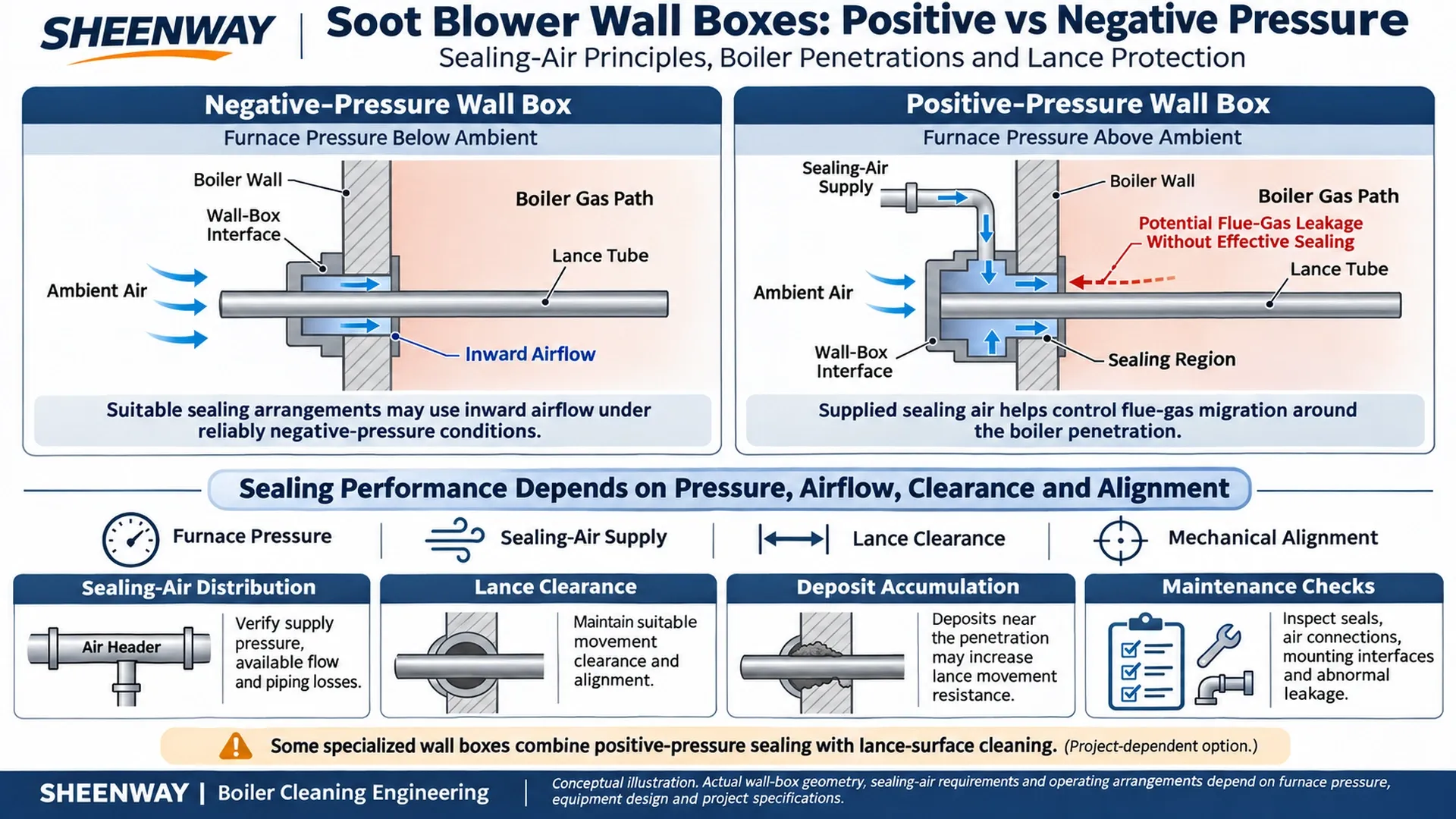
A soot blower must pass through the boiler casing to deliver its cleaning medium to the required heating surfaces. For retractable equipment, this opening must also accommodate lance movement while maintaining a suitable interface between the boiler atmosphere and the surrounding plant environment.
This interface is commonly called the soot blower wall box.
Although the wall box is smaller than the carriage, gearbox or lance assembly, its condition can directly affect equipment reliability.
If the wall-box sealing arrangement is unsuitable, hot flue gas and fly ash may escape through the boiler penetration or migrate into areas around the soot blower.
In boilers containing corrosive or deposit-forming gases, uncontrolled leakage can become a significant maintenance concern.
Positive-pressure wall boxes address this challenge by combining a suitable mechanical interface with a designed sealing-air supply.
Effective wall-box performance depends on the relationship between furnace pressure, sealing-air pressure and flow, lance clearance, mechanical alignment and operating conditions.
This article explains how positive-pressure wall boxes work, why sealing air is important, how different sealing arrangements compare and what engineers should check during maintenance or replacement.
1. What Is a Soot Blower Wall Box?
A wall box is the interface assembly installed at the opening through which a soot blower lance or cleaning element passes into a boiler.
Depending on the equipment design, it may perform several functions:
- Connect the soot blower to the boiler casing or wall sleeve.
- Provide an appropriate sealing arrangement around the moving lance.
- Help limit unwanted flue-gas leakage.
- Accommodate the required lance movement.
- Provide a structural connection or supporting interface.
- Incorporate sealing-air connections where required.
Babcock & Wilcox identifies the wall box as a component attached to the boiler opening that provides structural support and helps reduce flue-gas escape.
However, the exact supporting and sealing functions vary according to soot blower model and installation.
For long retractable soot blowers, the wall-box design must be compatible with the movement of the lance through the boiler-wall opening.
The clearance must be sufficient for the intended movement while allowing the sealing arrangement to perform correctly.
A wall box is not simply a hole cover or an ordinary pipe flange. It is part of the mechanical and gas-sealing interface between the soot blower and the boiler.
2. Positive-Pressure vs Negative-Pressure Wall Boxes
The pressure relationship between the boiler gas path and its surrounding environment is a major factor in wall-box selection.
Negative-Pressure Wall Box
In a reliably negative-pressure furnace, the gas-path pressure is below the surrounding atmospheric pressure.
Under suitable conditions, air tends to flow inward through available clearances instead of allowing flue gas to escape outward.
Some negative-pressure wall boxes use spring-loaded or floating sealing elements that accommodate lance movement.
A separate positive-pressure sealing-air supply may not be required for certain designs operating under reliably negative-pressure conditions.
However, a negative-pressure arrangement should not automatically be considered suitable when furnace pressure can become positive.
Positive-Pressure Wall Box
When the furnace gas pressure is above the surrounding atmospheric pressure, leakage through an inadequately sealed wall penetration can flow outward.
A positive-pressure wall box uses a suitable sealing arrangement together with sealing air supplied to the relevant interface.
The sealing-air system is designed to establish the required pressure and flow relationship around the penetration, helping reduce uncontrolled flue-gas escape.
Depending on the design, sealing air may be introduced into an annular space, chamber or other engineered sealing region.
The exact internal arrangement is manufacturer- and project-specific.
| Design Consideration | Negative-Pressure Arrangement | Positive-Pressure Arrangement |
|---|---|---|
| Furnace pressure | Reliably below surrounding pressure | May be above surrounding pressure |
| Principal sealing approach | Mechanical sealing supported by inward air movement where applicable | Mechanical sealing supported by supplied sealing air |
| Dedicated sealing-air supply | Not required for some designs | Generally required |
| Major leakage concern | Loss of intended draft or seal condition | Outward migration of hot flue gas and ash |
| Main engineering requirement | Suitable seal geometry and verified furnace conditions | Suitable seal geometry and verified air pressure and flow |
Wall-box selection should be based on the actual pressure conditions of the installation rather than a generic assumption about boiler type.
3. How Does Sealing Air Work?
A positive-pressure wall-box system introduces air into the designed sealing region around the boiler penetration.
The purpose is to establish a controlled pressure and flow condition that reduces the tendency of furnace gas to migrate outward through the opening.
In a simplified conceptual arrangement:
Sealing-Air Supply → Wall-Box Air Connection → Sealing Region Around the Lance → Controlled Airflow at the Penetration
This does not mean that every wall box is completely airtight.
Some designs intentionally allow sealing air to flow through controlled clearances.
Depending on the structure and local pressure distribution, portions of the supplied air may flow toward the boiler or through other designed paths.
The objective is to control the movement of gas through the interface.
For the arrangement to function as intended, the air supply must be suitable for the actual furnace pressure and sealing geometry.
The required performance depends on factors such as:
- Local furnace pressure.
- Transient pressure variations.
- Wall-box clearance and seal construction.
- Air supply pressure and available flow.
- Piping losses.
- Number of connected soot blowers.
- Expected operating and standby conditions.
A supply-pressure reading alone does not necessarily confirm that sufficient air reaches every wall box.
The complete distribution network should be considered.
4. Sealing Air, Purge Air and Blowing Steam: What Is the Difference?
These terms are sometimes used loosely in industrial discussions, but they describe different functions.
Sealing Air
Sealing air is supplied to the wall-box sealing region to help control flue-gas migration around the boiler penetration.
Its principal function is maintaining the required interface condition.
Protective or Scavenging Air
Some soot blower designs use protective or scavenging air to reduce the entry of furnace gas into internal equipment passages during standby.
This may involve a dedicated connection associated with the soot blower valve, lance or another part of the medium-delivery system.
Such protection is not automatically the same as wall-box sealing.
Blowing Steam
Blowing steam is the cleaning medium directed through the soot blower to remove deposits from boiler heating surfaces.
Its operating purpose, flow path and control sequence are different from those of sealing air.
Cleaning Medium for the Wall Box
Certain specialized wall-box designs also incorporate a cleaning function to reduce deposits around the moving lance.
This may use a separate medium or a project-defined operating sequence.
Not every positive-pressure wall box includes such a cleaning function.
The air or steam source may be shared in some projects, but the individual functions and flow paths must still be distinguished.
5. Selecting a Sealing-Air Source
Positive-pressure wall boxes require an appropriately engineered air supply.
Depending on the installation, possible sources may include:
- A suitably conditioned plant compressed-air system.
- A dedicated sealing-air blower.
- An approved source associated with the boiler air system.
- Another project-specific air supply arrangement.
The selected source must provide the required pressure and flow under the specified operating conditions.
The engineering review should consider:
Air Pressure
The required sealing condition must be maintained at the wall-box connection, accounting for the actual furnace pressure.
Airflow Capacity
The source must be able to supply the connected sealing points under the applicable simultaneous operating conditions.
Distribution Losses
Pressure drop through headers, branches, fittings and control components must be considered.
Air Quality
Where relevant to the equipment, moisture, oil and particulate contamination should be controlled according to the approved specification.
Availability
The effect of air-supply interruptions or reduced capacity should be addressed in the operating and protection philosophy.
There is no universal sealing-air pressure or consumption rate applicable to every positive-pressure wall-box installation.
These values must be established by engineering calculation and verified against the actual wall-box design.
6. Why Mechanical Clearance and Alignment Matter
A wall box must accommodate the required movement of the soot blower lance.
However, the opening cannot be designed without considering the sealing arrangement.
If clearances or alignment are unsuitable, several problems may occur.
Excessive Clearance
The sealing arrangement may require greater airflow or may fail to maintain the intended gas-control performance.
Insufficient Clearance
The lance may contact surrounding components, increasing friction and the risk of mechanical damage.
Incorrect Alignment
The lance can experience uneven loading or abnormal contact as it moves through the wall penetration.
Thermal Movement
The relative position of the boiler wall and soot blower support can change as the boiler heats and cools.
This is why wall-box installation should be reviewed together with lance alignment, front support, mounting geometry and boiler thermal expansion.
A leaking wall box is not always caused by insufficient sealing-air pressure.
Mechanical installation problems may be contributing to the fault.
7. Why Deposit Accumulation Can Cause Lance Jamming
In some boilers, flue-gas deposits can accumulate around the lance and wall-box interface.
This is particularly relevant to applications involving sticky, corrosive or alkali-rich deposits.
As deposits build up, the effective clearance around the lance may decrease.
The moving lance can then experience additional resistance when extending or retracting.
Possible consequences include:
- Abnormal contact around the wall penetration.
- Increased drive loading.
- Difficulty extending or retracting.
- Damage to sealing components.
- Accelerated wear of the lance surface.
- Recurring mechanical faults.
A standard sealing arrangement may help reduce flue-gas migration but may not remove deposits already accumulating on the lance exterior.
For this reason, some projects use wall-box configurations with an additional cleaning function.
The appropriate solution depends on the deposit characteristics, existing equipment and maintenance requirements.
8. Dual Positive-Pressure Cleaning Wall Boxes
A dual-function wall box is designed to address more than gas sealing.
Depending on its particular construction, it can provide separate functions for:
Positive-Pressure Sealing
Using an appropriate air supply to help control flue-gas migration around the penetration.
Lance-Surface Cleaning
Using a dedicated cleaning arrangement to help limit deposit accumulation around the moving lance.
These functions should not be confused.
Positive-pressure sealing does not automatically remove all deposits from the lance.
Likewise, a cleaning function does not eliminate the need for a suitable wall-box seal.
A SHEENWAY recovery-boiler retrofit involving 17 long retractable soot blowers used dual positive-pressure cleaning wall boxes to address sealing and alkali-deposit problems around the lance interface.
The project illustrates why a wall-box upgrade may be necessary even when the existing soot blower drive equipment remains operational.
However, dual-function wall boxes are not universally required.
Their application should be justified by the actual furnace environment, deposit behavior and equipment configuration.
9. Common Wall-Box Problems and Possible Causes
Wall-box problems may appear as gas leakage, ash accumulation or mechanical interference.
| Observed Problem | Possible Causes | Initial Engineering Review |
|---|---|---|
| Flue gas escaping near the penetration | Insufficient sealing air, damaged seal or unsuitable pressure conditions | Furnace pressure, sealing-air supply and seal condition |
| Ash accumulation around the wall box | Gas migration, deposit-forming conditions or inadequate local cleaning | Deposit characteristics and interface condition |
| Lance binds near the boiler wall | Misalignment, insufficient clearance or accumulated deposits | Lance alignment, wall-box opening and support geometry |
| Seal components wear repeatedly | Uneven contact, unsuitable clearance or installation problem | Seal condition and mechanical positioning |
| Sealing performance deteriorates during high load | Furnace-pressure changes or limited air capacity | Actual pressure conditions and distribution capacity |
| One wall box performs worse than others | Local branch restriction, air leakage or different interface condition | Branch supply and local mechanical condition |
| Excessive air consumption | Air leakage, unsuitable clearances or incorrect supply configuration | Header, branches and sealing interfaces |
These are diagnostic starting points.
A particular symptom does not prove one unique failure mechanism.
Inspection should correlate the observed condition with pressure data, airflow availability, installation drawings and actual equipment condition.
10. How Should Sealing-Air Distribution Be Evaluated?
For a boiler with many soot blowers, sealing-air performance becomes a system-level engineering issue.
The total supply requirement is influenced by the number of connections, individual wall-box requirements and operating conditions.
The distribution design should consider:
- Main air header capacity.
- Branch piping layout.
- Pressure losses.
- Isolation and maintenance provisions.
- Appropriate instruments, where required.
- Distribution to remote or high-resistance branches.
- Changes in furnace pressure.
- System behavior under air-supply faults.
A pressure indication near the supply blower may not represent the conditions at the most remote wall box.
Depending on the project, local measurements or other approved verification methods may be necessary.
SHEENWAY has documented a large recovery-boiler installation involving 84 long retractable soot blowers with a dedicated sealing and cleaning air network.
That project demonstrates the importance of coordinated distribution engineering when many wall-box sealing points share an air source.
Its specific equipment quantities and operating parameters are project-specific and should not be used as universal design values.
11. What Should Be Checked During Routine Inspection?
The inspection scope should follow the original equipment requirements and site maintenance procedures.
Typical review items may include:
| Inspection Area | Main Question |
|---|---|
| Wall-box housing | Is there evidence of distortion, cracks or abnormal leakage? |
| Sealing components | Are the components damaged, worn or contaminated? |
| Air connections | Are hoses, fittings and pipes intact? |
| Air supply | Is the specified pressure and flow available? |
| Lance clearance | Is there abnormal contact or restriction? |
| Mounting interfaces | Are connections and supports in acceptable condition? |
| Deposits | Is ash or scale accumulating around the opening? |
| Protective-air connections | Are separate protective-air functions operating as designed? |
| Monitoring and controls | Are relevant indicators, alarms and operating conditions functioning correctly? |
The exact inspection interval depends on the equipment and operating duty.
A wall box exposed to severe deposits or corrosive gas may require different monitoring from one operating under relatively clean conditions.
Inspection findings should be recorded so that recurring faults can be identified.
12. Maintenance Safety and Lance Removal
Wall-box maintenance may involve hazardous furnace gas, hot surfaces, moving equipment and pressurized air or steam.
Work should only begin under the plant's approved isolation and maintenance procedures.
Removing a lance or wall-box component can expose the boiler penetration.
Certain specialized wall boxes provide aspirating or purge-air functions for particular maintenance situations.
However, the presence of a sealing-air connection must never be treated as proof that a lance can be safely removed while the boiler remains in operation.
Any such activity requires an explicitly engineered and approved arrangement, a verified procedure and appropriate site authorization.
Personnel must not use an improvised air curtain as a substitute for safe isolation.
Before maintenance, the relevant electrical, steam, pneumatic, mechanical and furnace-atmosphere hazards must be assessed and controlled.
13. What Information Is Needed for Wall-Box Replacement?
Replacement wall-box compatibility involves both the boiler interface and the soot blower.
A technical inquiry should provide as much of the following information as possible.
| Required Information | Engineering Purpose |
|---|---|
| Original soot blower manufacturer and model | Identify the equipment family |
| Wall-box part number or reference | Identify the original arrangement |
| Positive or negative furnace-pressure condition | Establish the sealing concept |
| Furnace pressure at the installation point | Define operating requirements |
| Boiler-wall interface drawing | Confirm the actual wall penetration |
| Wall sleeve dimensions and length | Establish installation compatibility |
| Mounting dimensions and bolt pattern | Confirm mechanical fit |
| Lance outside diameter and movement | Confirm passage and sealing requirements |
| Wall-box seal configuration | Establish sealing compatibility |
| Air connection requirements | Confirm utility interfaces |
| Sealing-air design conditions | Support pressure and flow evaluation |
| Cleaning function, where applicable | Determine whether a dual-function design is required |
| Existing photographs or approved reference drawings | Support configuration verification |
For replacement projects, the boiler-wall interface drawing is particularly important.
It can identify the existing sleeve, penetration arrangement, mounting geometry and other details that affect installation.
The final design must also consider thermal movement, maintenance access and the applicable boiler construction requirements.
A wall box should not be selected solely from its external appearance or nominal lance diameter.
14. Commissioning and Functional Verification
After installing or replacing a wall box, the completed arrangement should be checked before normal operation.
Depending on the project, the verification may include:
- Confirmation of mounting geometry.
- Inspection of the installed sealing components.
- Verification of sealing-air piping and connections.
- Confirmation of the approved air-supply conditions.
- Checking for abnormal gas leakage.
- Verification of lance movement and clearance.
- Assessment of relevant cold and hot operating conditions.
- Confirmation of applicable protective-air functions.
- Verification of monitoring and alarm functions where provided.
A successful cold inspection does not necessarily establish performance at full operating temperature and furnace pressure.
Thermal movement and actual gas-pressure conditions may change the interface behavior.
The commissioning process should therefore reflect the approved plant requirements.
15. Positive-Pressure Wall Boxes in Soot Blower Retrofits
Replacing an older soot blower may require more than matching the original mechanical dimensions.
The boiler penetration, wall box, sealing-air network and lance configuration must function together.
For example, a replacement lance with a different outside diameter may require review of the wall-box sealing geometry.
A new carriage or support arrangement may affect the alignment of the lance through the wall opening.
An upgraded wall-box cleaning function may introduce different utility and control requirements.
SHEENWAY supports retrofit projects involving long retractable soot blowers, positive-pressure wall boxes, sealing-air equipment and application-specific interfaces.
For OEM-compatible replacement, the required configuration should be established from verified original equipment information and the actual boiler installation.
The objective is to achieve dimensional and functional compatibility while meeting the applicable sealing and operating requirements.
Conclusion
A soot blower wall box is a critical interface between the boiler atmosphere and the cleaning equipment.
In reliably negative-pressure installations, suitable mechanical arrangements may use inward airflow to help control gas leakage.
Positive-pressure installations generally require a designed sealing-air system to reduce the escape of furnace gas through the penetration.
Reliable performance depends on sealing-air pressure and flow, appropriate clearances, correct alignment, suitable installation interfaces and maintenance.
For deposit-prone applications, a wall-box cleaning function may also be needed to help limit lance interference and jamming.
The correct wall-box solution is determined by the actual furnace conditions and equipment interfaces—not by a universal design or fixed sealing-air setting.
SHEENWAY supports soot blower engineering, positive-pressure wall-box solutions and compatible replacement projects based on verified equipment and boiler-interface requirements.
Customers can provide the original soot blower model, boiler-wall interface drawings, lance dimensions, furnace-pressure conditions and sealing-air requirements for technical review.
More from Sheenway
Continue Reading
Soot Blower Commissioning Checklist: From Cold Tests to Hot Operation
Commissioning a soot blowing system requires more than checking motor operation. This guide covers pre-start inspection, mechanical alignment, steam piping, drainage, electrical controls, cold functional testing, hot commissioning and final acceptance for reliable boiler soot blower operation.
Read articleSoot Blower Steam Piping Thermal Expansion: Supports, Flexibility and Connection Loads
Thermal expansion in soot blower steam piping can impose unintended loads on valves, flanges and equipment connections. This guide explains pipe flexibility, anchors, guides, supports, expansion compensation and drainage considerations for reliable boiler soot blowing systems.
Read articleSoot Blower Steam Consumption and Header Sizing: What Engineers Should Verify
Steam soot blowing systems must supply the required pressure and mass flow to each operating blower. This guide explains how individual steam consumption, simultaneous demand, header sizing, pressure drop, drainage and control sequencing affect steam supply system design and retrofit decisions.
Read article