
SCR Catalyst Fouling and Cleaning: Why Direction and Cleaning Intensity Matter
SCR catalyst cleaning is not the same as cleaning a conventional boiler tube bank. Fly ash can restrict catalyst channels and increase pressure drop, while excessive or poorly directed cleaning can expose the catalyst to unnecessary mechanical stress. This article explains SCR fouling, controlled cleaning and the role of rake-type soot blowers.
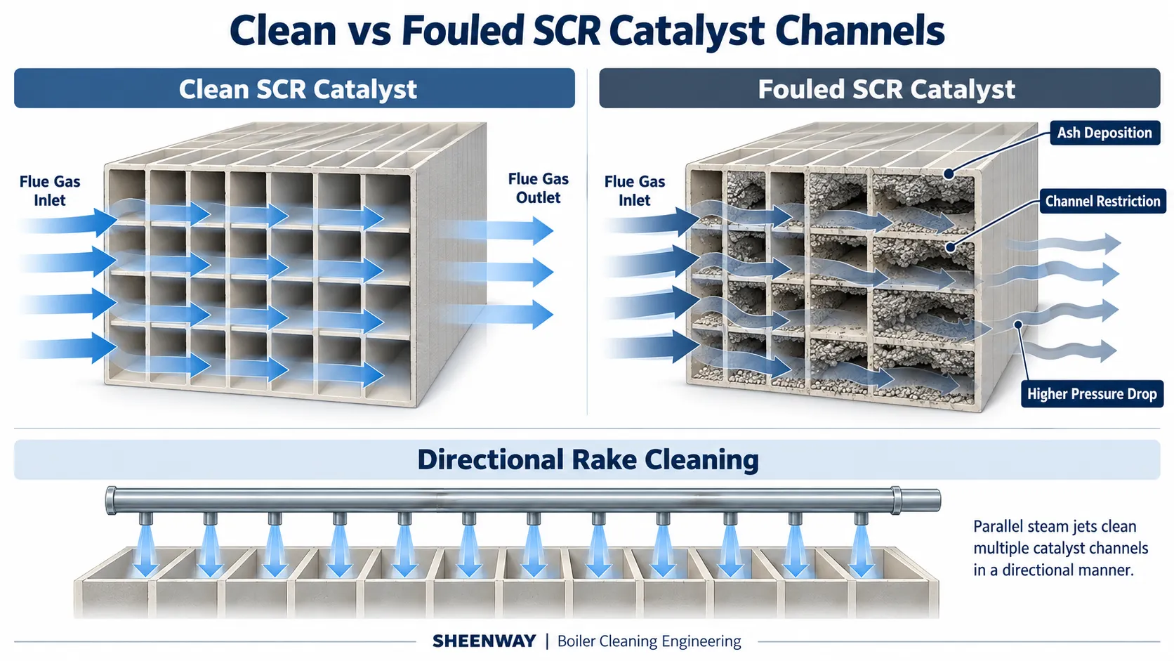
SCR Catalyst Fouling and Cleaning: Why Direction and Cleaning Intensity Matter
Selective Catalytic Reduction, or SCR, is widely used to reduce nitrogen oxide emissions from industrial flue gas.
Inside the SCR reactor, flue gas passes through catalyst elements while ammonia reacts with nitrogen oxides on the catalyst surface.
The catalyst therefore has two requirements that must be maintained at the same time:
the active surface must remain available for the chemical reaction, and the gas passages must remain sufficiently open for flue gas to pass through the reactor.
In high-dust applications, this creates a practical operating challenge.
Fly ash travels through the SCR reactor together with the flue gas. Particles can accumulate on catalyst surfaces or inside the passages, gradually restricting the available flow area.
EPA technical guidance identifies ash management, dust loading, catalyst pressure drop and catalyst deactivation as important SCR design and operating considerations.
Cleaning is therefore necessary in many SCR systems.
But an SCR catalyst should not simply be treated like another boiler tube bank.
The geometry is different, the substrate can be more sensitive to mechanical action, and not every form of catalyst deterioration can be removed by soot blowing.
That is why cleaning direction and cleaning intensity both matter.
What Happens When Fly Ash Accumulates on an SCR Catalyst?
SCR catalysts are commonly manufactured with numerous narrow gas passages to provide a large active surface area while allowing flue gas to move through the reactor.
In dusty flue gas, particles can gradually accumulate around these passages.
Mitsubishi Heavy Industries has documented how components in coal fly ash can adhere to the inner surface of honeycomb catalysts, mask active surfaces and form deposits along the gas path. Continued accumulation can restrict gas flow and contribute to deterioration of De-NOx performance.
From an operating perspective, physical deposition can produce several related problems:
- catalyst surfaces become partially masked;
- channels become progressively restricted;
- gas distribution through the catalyst may deteriorate;
- and pressure drop across the catalyst layer can increase.
EPA guidance likewise states that deposition of fly ash and other particulate matter increases catalyst pressure drop over time.
This means that catalyst cleaning is not simply about making the catalyst look clean.
It is also about maintaining the physical flow paths required for the SCR reactor to operate properly.
Fouling, Plugging and Poisoning Are Not the Same Problem
One of the most important distinctions in SCR maintenance is the difference between physical deposition and chemical deactivation.
They may occur at the same time, but they are not the same failure mechanism.
Fouling and Masking
Particles accumulate on the catalyst surface and reduce access to the active area.
Some of this material may be removable by appropriate online cleaning.
Channel Plugging
Ash or other deposits physically restrict the catalyst passages.
This can increase pressure drop and disturb gas distribution.
Chemical Poisoning
Certain fuel- and ash-derived species can react with or block the chemically active sites of the catalyst.
EPA lists chemical poisoning separately from fouling, plugging, erosion and thermal degradation when discussing major SCR catalyst-deactivation mechanisms.
This distinction is critical because a soot blower can remove removable physical deposits, but it cannot automatically restore catalyst chemistry that has been permanently deactivated.
If catalyst activity is declining because of chemical poisoning, simply increasing soot-blowing frequency may not solve the real problem.
Why SCR Cleaning Cannot Be Treated Like Ordinary Tube Cleaning
A superheater or reheater soot blower is generally intended to direct a high-energy cleaning jet toward deposits on metal heat-transfer surfaces.
SCR catalyst cleaning requires a different balance.
The catalyst must be cleaned strongly enough to remove loose particulate, but the cleaning action should not introduce unnecessary mechanical or erosive loading.
Babcock & Wilcox describes steam or air soot blowing as a common SCR catalyst-cleaning method and notes that the cleaning velocity is lower than in conventional boiler sootblower applications in order to reduce the risk of mechanical or erosive damage to the catalyst substrate.
This leads to a fundamental engineering principle:
More cleaning energy is not automatically better cleaning.
The target is not maximum impact.
The target is sufficient energy to remove the deposit while respecting the mechanical characteristics of the catalyst.
Why Cleaning Direction Matters
SCR catalyst elements contain structured flow passages.
The cleaning objective is therefore different from attacking deposits on a relatively open tube surface.
Cleaning energy needs to be directed toward the regions where ash accumulates and toward the catalyst flow passages that require clearing.
A conventional rotating lance can be highly effective in boiler tube-bank applications because rotation helps distribute the cleaning jet around a broad area.
But SCR catalyst geometry can require a more controlled directional approach.
This is the engineering reason behind a rake-type soot blower.
SHEENWAY's SW-SRKS is a retractable rake-type soot blower intended for SCR catalyst cleaning. Its in-furnace rake does not rotate; instead, the rake arrangement directs the blowing medium toward the required cleaning direction while the lance travels through the cleaning zone.
The design principle is straightforward:
when the target geometry is directional, the cleaning system should also be directional.
What Is a Rake-Type Soot Blower?
A rake-type soot blower is a retractable cleaning device in which the lance arrangement differs from a conventional rotating long retractable soot blower.
Rather than relying on lance rotation to distribute the cleaning jet, a rake incorporates a defined nozzle arrangement aimed toward the target surfaces.
The system then moves through the required cleaning path.
EPA technical guidance specifically identifies retractable rake-type soot blowers using steam or air as a technology used in SCR designs and notes that they may be installed above catalyst layers.
For SCR applications, this arrangement provides two important engineering advantages:
controlled cleaning direction
and
repeatable coverage across the catalyst layer.
However, actual nozzle quantity, spacing, cleaning medium conditions, travel and installation geometry must still be determined for the specific reactor.
A rake configuration is not a universal fixed geometry.
Uniform Coverage Matters More Than Maximum Jet Force
Imagine a catalyst layer where one region receives repeated direct cleaning while another region is barely reached.
Increasing total cleaning pressure does not necessarily correct that problem.
It may simply increase the energy applied to the already well-covered area.
This illustrates why coverage and direction must be considered together with pressure.
A well-designed SCR cleaning system should ask:
Where are the catalyst channels?
Where is ash likely to accumulate?
What direction allows the cleaning jet to reach those regions?
How much overlap is required between adjacent cleaning paths?
What distance exists between the rake and catalyst layer?
What cleaning-medium conditions are appropriate for the catalyst design?
These are geometric and system-design questions, not simply pressure-setting questions.
Steam Quality Also Matters
When steam is used for SCR catalyst cleaning, its condition is another important consideration.
B&W notes that moisture in cleaning steam can be undesirable because droplets may contribute to erosion or thermal shock on some catalyst designs.
This is an important distinction.
The nominal steam pressure alone does not completely define the cleaning medium.
Condensate management and steam condition can also affect how the cleaning energy reaches the catalyst.
For this reason, a cleaning problem should not automatically be diagnosed as:
“the pressure is too low.”
The complete steam and soot-blowing system should be evaluated.
Differential Pressure Is Useful — But It Is Not a Complete Diagnosis
Because channel restriction affects gas flow, pressure drop across an SCR catalyst is an important operating parameter.
EPA guidance specifically notes that particulate deposition on the catalyst can increase pressure loss.
However, an increase in differential pressure should not automatically be interpreted as proof that a soot blower has failed.
Possible causes can include changes in:
- particulate loading;
- deposit characteristics;
- gas flow;
- catalyst condition;
- cleaning coverage;
- or other reactor operating conditions.
The useful question is therefore not simply:
“Is differential pressure high?”
It is:
“Has the pressure-drop trend changed, and does the catalyst respond to cleaning as expected?”
That distinction is useful when determining whether the problem is insufficient soot blowing, changing deposits or a broader SCR issue.
Why More Frequent Cleaning Is Not Always the Solution
If catalyst pressure drop begins increasing, the intuitive response may be to operate the soot blowers more frequently.
That can be appropriate when insufficient removal of loose ash is actually the problem.
But frequency is only one variable.
If the rake is not covering the required region, more cycles repeat the same coverage problem.
If deposits have become strongly bonded, additional online blowing may provide diminishing benefit.
If the catalyst has experienced chemical poisoning, additional soot blowing cannot restore the lost active chemistry.
And if cleaning energy is excessive, increasing the number of cycles may expose the catalyst to unnecessary mechanical action.
Therefore, cleaning frequency should be considered together with:
deposit type + coverage + direction + cleaning-medium condition + catalyst response.
When Soot Blowing Is Not Enough
Online soot blowing is primarily a deposit-control method.
It is not a universal catalyst-regeneration process.
Mitsubishi Heavy Industries has described dedicated chemical-cleaning technology for spent SCR catalysts that addresses catalyst contaminants beyond what simple physical cleaning can remove.
That distinction helps define the limits of a soot blower.
If the problem is loose fly ash blocking passages, online cleaning may be directly relevant.
If the catalyst has undergone significant chemical deactivation, thermal degradation or irreversible damage, the required response may involve catalyst testing, offline cleaning, regeneration or replacement rather than simply changing the soot-blowing schedule.
Correct diagnosis therefore comes before cleaning optimization.
What Should Be Confirmed for an SCR Soot Blower Project?
For a new installation or retrofit, the cleaning system should be designed around the actual SCR geometry.
Important information normally includes:
Catalyst arrangement
The number of layers, module dimensions and gas-passage orientation affect cleaning coverage.
Rake travel and installation position
The cleaning assembly must physically cover the required catalyst area.
Required cleaning direction
The nozzle arrangement should correspond to the target catalyst geometry.
Deposit characteristics
Loose fly ash and more strongly bonded deposits may respond differently.
Available cleaning medium
Steam or compressed-air conditions need to be confirmed for the project.
Distance to the catalyst
Stand-off distance influences jet behavior and coverage.
Maintenance access
The system should allow inspection and servicing without creating unnecessary maintenance difficulty.
For retrofit projects, existing interfaces, support geometry and control requirements also need to be verified.
The objective is not merely to install a rake-type soot blower.
It is to create the correct cleaning field for the specific SCR reactor.
SCR Cleaning Should Protect Both Flow and Catalyst Integrity
The purpose of catalyst cleaning can be summarized as two simultaneous requirements:
keep the flow passages sufficiently clear
while
avoiding unnecessary damage to the catalyst structure.
Too little effective cleaning can allow ash to accumulate and pressure drop to rise.
Poorly directed cleaning can leave some catalyst areas insufficiently covered.
Excessive cleaning intensity can create its own mechanical risks.
And no amount of soot blowing can reverse every form of catalyst deactivation.
This is why SCR catalyst cleaning should be treated as a controlled engineering process rather than simply another high-pressure cleaning application.
Conclusion
SCR catalyst fouling is not only a surface-cleanliness issue.
Fly ash can mask catalyst surfaces, restrict gas passages and increase reactor pressure drop. At the same time, SCR catalysts require a more controlled cleaning approach than many conventional boiler heat-transfer surfaces.
The engineering objective is therefore not maximum cleaning force.
It is:
sufficient cleaning energy + correct direction + appropriate coverage.
This is the application logic behind rake-type soot blowers.
SHEENWAY's SW-SRKS uses a non-rotating rake arrangement to direct cleaning toward the required target region, making it suitable for SCR catalyst applications where cleaning direction is a critical part of the system design.
For a reliable SCR cleaning solution, soot blower selection should therefore begin with the catalyst geometry, deposit behavior and actual operating conditions—not simply with a pressure value or equipment model number.
More from Sheenway
Continue Reading
Retractable Boiler Temperature Probe: Why It Matters During Boiler Startup
During boiler startup, furnace exit gas temperatures can rise before sufficient steam cooling is established in certain heating surfaces. A retractable boiler temperature probe positions a thermocouple in the gas path to provide temperature information for operating decisions. This guide explains the working principle, startup applications, measurement limitations and selection requirements of the SHEENWAY SW-MTPS.
Read articleRake-Type Soot Blower Design for SCR: Nozzle Layout, Travel and Support
Rake-type soot blowers use non-rotating, axially moving cleaning assemblies to direct steam or compressed air toward SCR catalysts and other structured surfaces. This guide explains nozzle layout, travel, support and guide arrangements, cleaning-medium conditions and the engineering checks required before selecting or replacing a rake-type soot blower.
Read articleMulti-Medium Retractable Soot Blowers: When Steam Alone Is Not Enough
Steam soot blowing is effective for many boiler cleaning applications, but certain gypsum, salt and strongly bonded deposits may require additional cleaning methods. This guide explains how multi-medium retractable soot blowers combine different cleaning options, when water washing may be considered, and how engineers select an appropriate solution for gas-gas heaters and air preheaters.
Read article