
Why Steam Drainage Matters in Soot Blowing Systems
Condensate in soot blowing steam lines can cause water hammer, unstable steam delivery and accelerated erosion of boiler heating surfaces. This technical guide explains why steam-line warm-up and drainage are necessary, how condensate forms, and what engineers should check in drainage piping, valves and control sequences.
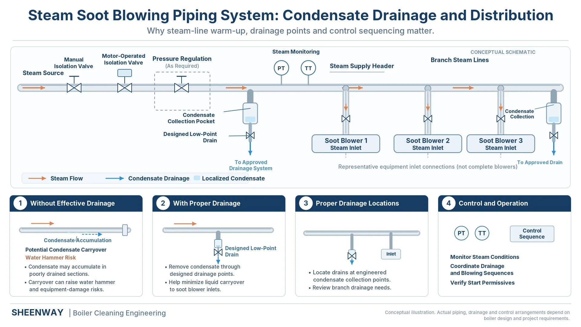
A steam soot blower depends on more than its lance tube, nozzles, carriage and drive mechanism.
The condition of the steam reaching the soot blower is equally important.
Even when the supply pressure meets the specified value, accumulated condensate in the steam piping can create operating problems. These may include water hammer, unstable steam delivery, valve damage and accelerated erosion of boiler heating surfaces.
For this reason, steam drainage is not simply an accessory function of a soot blowing system.
Effective condensate removal is an essential part of reliable and safe steam soot blowing.
This article explains how condensate forms, why it must be removed before steam blowing, and which piping, drainage and control-system factors engineers should evaluate.
1. Why Does Condensate Form in Soot Blower Steam Lines?
Steam piping continuously exchanges heat with its surroundings.
When steam enters a relatively cold pipe, part of its thermal energy is transferred to the pipe wall and surrounding environment.
Under appropriate thermodynamic conditions, this heat loss causes some steam to condense into liquid water.
The condensate may collect along the bottom of the pipe or accumulate at low points.
The problem becomes particularly relevant in soot blowing systems because steam consumption is often intermittent.
Unlike equipment that receives a continuous steam supply, many soot blowers operate for relatively short periods and remain inactive between cleaning cycles.
During these inactive periods, steam remaining in certain sections of the piping may cool.
After shutdown or a prolonged standby period, condensate may remain inside the steam distribution system.
When the steam supply is reopened, the initial steam flow may encounter this accumulated water.
Without adequate drainage, some condensate can be carried downstream toward the soot blower valves and nozzles.
This is why steam-line drainage must be evaluated as part of the complete soot blowing system, not only at the individual blower.
2. What Happens When Condensate Is Carried into the Steam Flow?
Water and steam behave differently.
Steam is compressible, whereas liquid water is comparatively incompressible and much denser.
When high-velocity steam picks up accumulated condensate, the liquid may be carried through the piping as droplets, a film or larger slugs of water.
These can create several problems.
Water Hammer
Moving slugs of condensate may strike pipe bends, valves and fittings, generating sudden mechanical loads and pressure transients.
Valve and Piping Damage
Repeated liquid impact can damage valves, fittings and other components.
Wet Steam Delivery
Entrained moisture changes the condition of the cleaning medium reaching the soot blower.
Boiler Tube Erosion
High-velocity liquid droplets directed toward heating surfaces can increase localized erosion risks.
These problems do not necessarily occur together or with the same severity.
Their consequences depend on the amount of condensate, steam velocity, piping geometry and equipment operating conditions.
However, all four demonstrate why proper steam drainage is an important engineering requirement.
3. Why Wet Steam Can Damage Boiler Heating Surfaces
A soot blower generates a high-velocity jet to remove ash deposits from boiler heating surfaces.
The cleaning action depends on nozzle geometry, pressure, flow, blowing distance and the movement of the lance.
If the steam contains excessive liquid water, droplets can travel with the cleaning jet and strike nearby boiler tubes.
The National Board of Boiler and Pressure Vessel Inspectors specifically identifies soot blowing with wet steam as a cause of tube damage.
Its technical guidance notes that inadequate warming and drainage of soot blower steam lines are common contributors to wet-steam conditions.
The risk can be particularly serious when a jet is incorrectly aligned and directly strikes a tube surface.
Babcock & Wilcox also identifies soot-blowing steam impingement as a potential contributor to boiler tube erosion and, under some conditions, associated thermal fatigue.
The important engineering conclusion is:
Steam pressure alone does not establish that the cleaning medium is suitable for soot blowing.
Steam condition, condensate removal, nozzle alignment and the actual jet-to-tube relationship must be considered together.
4. Steam-Line Warm-Up and Drainage Are Related but Different
Steam-line warm-up and condensate drainage are closely connected, but they serve different functions.
Warm-up raises the temperature of the steam piping toward the required operating condition.
Drainage removes liquid condensate from the system.
During initial warm-up, cold pipe walls can cause substantial condensation.
Therefore, a warm-up procedure must provide a suitable path for condensate to leave the piping.
Simply allowing steam into a cold line for a fixed period does not prove that the line has been drained adequately.
A proper system needs an arrangement that can remove condensate while the piping warms.
In an engineered soot blowing sequence, the steam supply, pressure regulation, drainage valves and relevant instrument signals should operate according to the approved control logic.
Soot blowing should only be permitted once the specified operating conditions and required permissives have been satisfied.
The exact warm-up procedure, drainage duration and valve sequence depend on the installation.
They should not be copied from another project without engineering verification.
5. Where Should Drainage Points Be Installed?
Condensate removal depends heavily on piping geometry.
Because liquid water is affected by gravity, it tends to collect at low points in a piping system.
A drainage arrangement should therefore consider the locations where condensate is most likely to accumulate.
Relevant areas may include:
- Low points in the steam distribution piping.
- Locations affected by changes in pipe elevation.
- Sections upstream of closed control or isolation valves where condensate may collect.
- Branch lines that remain inactive between soot blowing cycles.
- Designated drainage locations associated with pressure-reducing or steam-conditioning equipment.
Spirax Sarco emphasizes the importance of correctly positioned drainage points, suitable drain pockets and condensate-removal arrangements in steam distribution systems.
It also explains that inadequate drainage may result in water hammer, erosion and damage to downstream equipment.
For a soot blowing system, the exact arrangement must be determined from the applicable piping design.
Drainage points should not be added or relocated solely according to a generic illustration.
6. Why Pipe Slope and Supports Matter
A drainage valve cannot remove water effectively if condensate is trapped elsewhere in the piping.
Correct pipe slope helps condensate move toward designated drainage points.
Pipe supports also matter because sagging pipes can create unintended low points.
These locations may trap condensate even when the original design includes suitable drain valves.
Spirax Sarco's general steam-distribution guidance discusses pipe fall, drainage intervals, low-point traps and appropriate pipe supports.
However, the recommended slope for a particular industrial steam-distribution system is not automatically the specified slope for every soot blowing installation.
For example, the required arrangement may be influenced by operating pressure, pipe diameter, steam flow direction, thermal expansion and site constraints.
Therefore, engineers should follow the approved project piping drawings and applicable design requirements.
The central principle is:
The piping layout must allow condensate to reach the intended drainage equipment without creating unintended water-retention points.
7. What Drainage Arrangements Can Be Used?
Soot blowing steam systems may use different condensate-drainage arrangements.
The appropriate choice depends on operating conditions, required automation and piping-system design.
Common arrangements include:
Temperature-Controlled Drain Valves
Valve operation is associated with a specified temperature condition.
Depending on the design, drainage remains available during warm-up until the required conditions are reached.
Timed Motorized Drain Valves
A control system operates a motorized valve according to an established drainage sequence.
The sequence must be developed for the actual equipment and operating conditions.
Drainage Valves Combined with Steam Traps
Some systems incorporate a steam trap or another engineered continuous-drainage arrangement to remove condensate that may form during operation.
Other Project-Specific Arrangements
Additional drainage equipment may be appropriate depending on the steam source, piping network and operational requirements.
No single drainage method should be described as universally superior.
The selection should consider drainage capacity, operating pressure, condensate load, reliability, maintenance requirements and control integration.
8. Why Drainage Must Be Included in Control Logic
Modern soot blowing systems often coordinate several functions through a PLC or DCS.
These may include:
- Main steam isolation.
- Pressure regulation.
- Steam-line warm-up.
- Condensate drainage.
- Drain-valve position confirmation.
- Steam pressure and temperature monitoring.
- Soot blower start permissives.
- Sequential blower operation.
For example, an automatic soot blowing system may first establish the appropriate steam supply and warm-up conditions, then complete its required drainage sequence before allowing the blowers to operate.
Some systems also use temperature-related permissives, valve-position feedback or other conditions as part of this logic.
However, a temperature reading or an elapsed timer alone does not always prove that liquid condensate has been completely removed.
Instrument readings must be interpreted according to the actual equipment design.
Drainage permissives are part of the protection and operating philosophy of the system, not merely a countdown timer.
The exact sequence should follow the approved project control documentation.
9. Steam Pressure Reduction Does Not Replace Drainage
Many industrial boilers supply steam at pressures higher than those required at the soot blower.
A pressure-reducing station may therefore be installed between the steam source and the soot blowing network.
Depending on the design, temperature-control equipment may also be included.
However, pressure regulation and drainage perform different functions.
Pressure regulation establishes the required downstream pressure.
Drainage removes accumulated liquid water.
A pressure-reducing station does not automatically remove all condensate from the downstream piping.
Similarly, an acceptable pressure indication does not prove that the entire steam line is free from liquid water.
Steam temperature, pressure, piping conditions and drainage performance should therefore be evaluated together.
This is particularly relevant to systems where steam flow changes substantially as individual soot blowers start and stop.
10. How Should a Drainage Problem Be Investigated?
If a soot blowing system exhibits abnormal noise, unstable operation or evidence of moisture carryover, the cause should be investigated systematically.
Potential areas of review include:
| Observation | Possible Investigation |
|---|---|
| Banging or vibration during steam admission | Condensate accumulation, rapid valve opening, inadequate warm-up or piping conditions |
| Repeated moisture carryover | Drainage performance, steam source condition and condensate collection points |
| Unstable steam conditions | Pressure regulation, temperature behavior, intermittent demand and drainage |
| Drain valve fails to operate as intended | Actuator, power supply, control signal, valve condition and position feedback |
| Condensate accumulation after shutdown | Pipe slope, low points, leakage paths and drainage arrangement |
| Localized boiler tube erosion | Soot blower alignment, nozzle orientation, steam condition and operating history |
These are diagnostic starting points, not proof of a specific failure mechanism.
For example, pipe vibration may have causes other than water hammer.
Likewise, boiler tube erosion can involve fly ash, steam jets, nozzle alignment and other operating conditions.
Any suspected abnormality must be handled according to the plant's approved operating and maintenance procedures.
Maintenance of pressurized steam equipment requires proper isolation and verification of a safe condition before inspection or repair.
11. What Should Engineers Check During a Retrofit?
When replacing or upgrading a steam soot blowing system, the piping and drainage design should be reviewed together with the soot blowers.
A practical engineering checklist includes:
Steam source
Confirm the available pressure, temperature and expected operating conditions.
Steam demand
Review the number of soot blowers, operating sequence and maximum simultaneous demand.
Piping geometry
Identify pipe elevations, low points, branch connections and support conditions.
Drainage equipment
Check the type, location, capacity and intended operating principle of drain valves and traps.
Instrumentation
Confirm relevant temperature, pressure and valve-position signals.
Control sequence
Verify warm-up, drainage and blowing permissives against the approved logic.
Maintenance access
Ensure that valves, instruments and drainage equipment can be inspected and serviced safely.
Existing operating problems
Review maintenance records, abnormal noise, moisture carryover and tube-inspection findings.
A retrofit that changes only the soot blower machines while leaving an inadequate condensate-drainage arrangement unchanged may fail to address an important system-level problem.
12. Why Drainage Engineering Matters in Real Retrofit Projects
Steam drainage is not only a theoretical concern.
In SHEENWAY's published case involving the modernization of 150 soot blowers across three industrial boilers, steam piping and drainage formed part of the overall system assessment.
The project included modifications to selected branch pipes, valves and drainage arrangements.
In one project-specific section, the drainage valve size was increased from DN32 to DN50 as part of the system optimization.
The engineering objective was to improve the ability to remove condensate and reduce unnecessary water retention in the soot blowing steam network.
However, DN50 should not be interpreted as a standard drainage-valve size for other boiler installations.
Drainage capacity and piping dimensions must be determined from the actual condensate load, pressure conditions and approved system design.
The broader lesson is that reliable soot blowing depends on the entire steam supply and drainage network, not simply on the number or model of soot blowers installed.
13. What Should Be Verified During Commissioning?
Before a new or modified soot blowing system enters service, the project commissioning procedure should verify the relevant steam-supply and drainage functions.
Depending on the design, these may include:
- Steam-piping installation and inspection.
- Specified pipe supports and expansion allowances.
- Drain-point accessibility and discharge arrangements.
- Drain-valve operation and position feedback.
- Pressure and temperature instrumentation.
- Warm-up and drainage control sequences.
- Required start permissives and protective functions.
- Stable operating conditions during the approved functional test.
Commissioning should establish that the drainage system performs its intended function under the specified conditions.
A drain valve that opens and closes correctly is only one part of this verification.
The design must also provide a suitable path for condensate to reach the valve and be discharged safely.
Conclusion
Steam soot blowing relies on the controlled delivery of an appropriate cleaning medium to the soot blower nozzles.
Condensate accumulation can interfere with this process and introduce significant safety and reliability risks.
Inadequate drainage may contribute to water hammer, unstable steam delivery, damage to valves and piping, and accelerated boiler tube erosion when liquid water is carried into the cleaning jet.
For this reason, steam-line warm-up, drainage-point arrangement, pipe slope, valve selection and control-system permissives must be considered as parts of one coordinated system.
The central engineering principle is simple:
A properly selected soot blower cannot compensate for an inadequately designed or operated steam supply and drainage system.
For new installations and retrofit projects, SHEENWAY evaluates steam piping, drainage arrangements, operating conditions and equipment interfaces as part of the wider boiler-cleaning system.
Reliable soot blowing begins before steam reaches the lance tube.
More from Sheenway
Continue Reading
Soot Blower Commissioning Checklist: From Cold Tests to Hot Operation
Commissioning a soot blowing system requires more than checking motor operation. This guide covers pre-start inspection, mechanical alignment, steam piping, drainage, electrical controls, cold functional testing, hot commissioning and final acceptance for reliable boiler soot blower operation.
Read articleSoot Blower Steam Piping Thermal Expansion: Supports, Flexibility and Connection Loads
Thermal expansion in soot blower steam piping can impose unintended loads on valves, flanges and equipment connections. This guide explains pipe flexibility, anchors, guides, supports, expansion compensation and drainage considerations for reliable boiler soot blowing systems.
Read articleSoot Blower Steam Consumption and Header Sizing: What Engineers Should Verify
Steam soot blowing systems must supply the required pressure and mass flow to each operating blower. This guide explains how individual steam consumption, simultaneous demand, header sizing, pressure drop, drainage and control sequencing affect steam supply system design and retrofit decisions.
Read article