
Waste-to-Energy Boiler Soot Blowing Retrofit: 9 Long Retractable Soot Blowers for Corrosive Flue Gas Conditions
A steam soot blowing system retrofit for a waste-to-energy boiler using 9 SW-SLRM long retractable soot blowers across the third-pass superheater and economizer sections, with positive-pressure sealing, protective air, steam piping and DCS-integrated control.
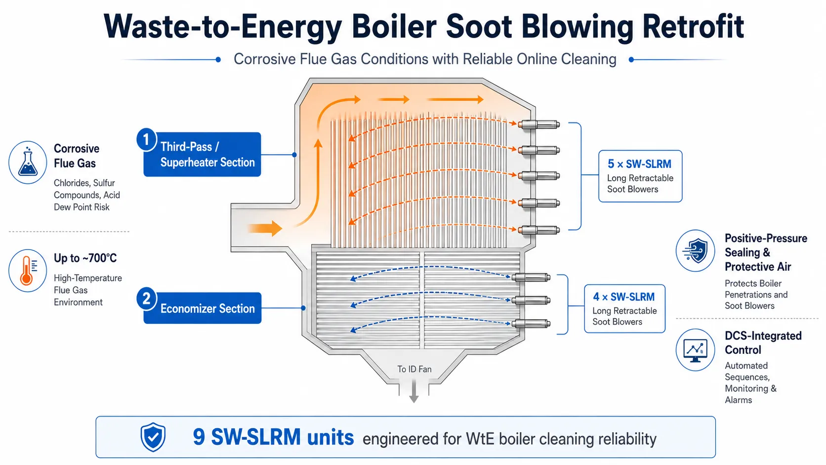
A soot blowing system for a waste-to-energy boiler must operate under conditions that are significantly different from those of many conventional industrial boilers.
High flue-gas temperatures, corrosive combustion products, complex heating-surface arrangements and the need for reliable online cleaning all place additional requirements on soot blower design, sealing, materials, steam conditions and control strategy.
In this retrofit project, SHEENWAY provided a complete steam soot blowing solution for a waste-to-energy incineration boiler at an environmental energy facility in southeastern China.
The project covered the third-pass superheater and economizer sections and included 9 SW-SLRM Long Retractable Soot Blowers, together with steam piping, drainage, positive-pressure sealing, protective air, electrical systems, DCS-integrated controls, installation support and commissioning.
The objective was not simply to install new soot blowers, but to establish a reliable cleaning system capable of operating under the corrosive and high-temperature conditions associated with waste incineration.
Project Overview
The soot blowing system was designed for two principal boiler cleaning zones:
- 5 SW-SLRM Long Retractable Soot Blowers for the third-pass and superheater section
- 4 SW-SLRM Long Retractable Soot Blowers for the economizer section
A total of:
9 SW-SLRM Long Retractable Soot Blowers
were incorporated into the retrofit.
The project-specific insertion length was approximately:
- 4.3 m for the superheater area
- 2.4 m for the economizer area
The system was designed to provide approximately 360° blowing coverage with an effective cleaning radius of about 2 meters, while the final blowing parameters were determined according to the actual flue-gas temperature, deposit characteristics and heating-surface arrangement.
The overall project scope included:
- Soot blower engineering and equipment supply
- Boiler interface design
- New soot blower openings and sealing arrangements
- Steam supply piping
- Drainage piping
- Valves and instrumentation
- Positive-pressure wall boxes
- Protective and sealing air system
- Electrical cabling
- PLC-based control system
- DCS communication and integration
- Cold commissioning
- Hot commissioning
- Technical documentation
- On-site installation and commissioning support
The Engineering Challenge: Corrosive Waste-Incineration Flue Gas
One of the most important characteristics of this project was the flue-gas environment.
Unlike many conventional boiler applications, the technical conditions specifically identified the waste-incineration flue gas as corrosive.
The maximum flue-gas temperature in the third-pass area was approximately 700°C, while different heating-surface sections operated under significantly different thermal conditions.
For a retractable soot blower, this means that the lance tube, nozzle assembly, wall interface and sealing system cannot be selected solely according to mechanical dimensions.
The engineering design must also account for:
- Flue-gas temperature
- Corrosive gas constituents
- Deposit characteristics
- Lance exposure time
- Material resistance
- Nozzle configuration
- Boiler-wall sealing
- Cleaning intensity
The objective is to provide sufficient cleaning energy without exposing the boiler tubes to unnecessary erosion or mechanical damage.
This balance between cleaning effectiveness and heating-surface protection was an important design consideration throughout the project.
Why SW-SLRM Long Retractable Soot Blowers Were Selected
The project utilized SW-SLRM Long Retractable Soot Blowers for both the third-pass superheater and economizer sections.
During operation, the lance tube extends into the boiler while rotating, allowing the nozzle jets to follow a controlled cleaning path across the heating surfaces.
The lance then retracts from the high-temperature gas path after the blowing cycle is completed.
This operating principle is particularly valuable where the soot blower must clean relatively deep heating-surface sections while minimizing the amount of time the lance remains permanently exposed to the flue gas.
For this project, the configuration provided:
- Full retractable movement
- 360° blowing coverage
- Approximately 2 m effective cleaning radius
- Project-specific lance lengths
- Adjustable blowing conditions
- Reliable forward and reverse travel
- Automatic return to the standby position
The final nozzle diameter, blowing-medium pressure and steam consumption were selected according to actual boiler conditions rather than simply applying one fixed standard parameter.
Material Selection for High-Temperature and Corrosive Service
Material selection was another important part of the engineering design.
The soot blower inner pipe, lance tube and nozzle components were required to operate under elevated temperatures while exposed to waste-incineration flue gas.
The project therefore specified stainless-steel materials for key lance components and required the actual lance and nozzle configuration to be adjusted according to the temperature at each installation position.
This is especially important in waste-to-energy applications.
A component that performs satisfactorily in a conventional coal-fired or lower-temperature boiler environment may experience substantially different corrosion and thermal exposure in a waste-incineration boiler.
For this reason, SHEENWAY evaluates material selection together with:
- Local flue-gas temperature
- Chemical environment
- Expected exposure duration
- Mechanical loading
- Required service life
- Nozzle operating conditions
rather than treating material grade as an isolated specification.
Positive-Pressure Wall Boxes and Sealing Air
A particularly important feature of this project was the soot blower sealing system.
Each soot blower was equipped with a positive-pressure wall box connected to compressed air.
The purpose of this arrangement is to maintain controlled positive pressure around the boiler-wall penetration and reduce the possibility of corrosive flue gas and fly ash migrating outward through the soot blower interface.
The retrofit also included a dedicated protective-air arrangement.
Compressed air was connected from the plant's existing protective-air header to the individual soot blowers, while the system design also included an additional sealing-air fan and associated piping where required.
This served several functions:
- Protecting the soot blower wall interface
- Reducing flue-gas and ash leakage
- Providing a cleaner environment around the penetration
- Supporting long-term sealing performance
- Protecting internal soot blower components when the blower is not operating
The soot blower valve was also equipped with an air-introduction arrangement.
When soot blowing was not in operation, compressed air could be introduced to help dry and cool the valve and lance assembly.
For a corrosive waste-incineration environment, this sealing and protective-air strategy is an important part of equipment reliability.
Steam Supply and Drainage Engineering
The available steam source for the project was approximately:
- 4.0 MPa
- 400°C
However, soot blower performance depends on the actual steam conditions reaching the nozzle, rather than simply the conditions at the plant steam header.
The project therefore included engineering and supply of the complete steam distribution system between the main steam connection and the individual soot blowers.
The system included:
- Main isolation valve
- Motorized shut-off valve
- Motorized regulating valve
- Drain valves
- Check valves
- Pressure monitoring
- Temperature monitoring
- Associated piping and fittings
- Supports and expansion considerations
The piping arrangement was required to account for both thermal expansion and drainage slope.
This is important because condensate remaining in a steam soot blowing line can result in unstable blowing-medium conditions during startup of a blowing cycle.
The system was therefore designed so that steam supply, drainage and soot blower operation functioned as one coordinated system.
Preventing Steam and Drainage Impact on Heating Surfaces
The technical design also considered the relationship between the soot blowing system and the surrounding boiler tubes.
Drainage arrangements were required to prevent condensate discharge from adversely affecting heating surfaces.
At the same time, blowing pressure and nozzle configuration had to provide sufficient ash-removal capability without introducing excessive jet impact.
This illustrates an important principle of steam soot blowing:
More blowing energy is not automatically better cleaning.
The correct solution is to deliver the required jet energy to the deposit while controlling the mechanical and thermal impact on the heating surface.
Boiler Interface and Retrofit Engineering
Because this was an existing-boiler retrofit, the new soot blowing system had to be integrated into the existing boiler structure.
The project required new openings at specified elevations in both the superheater and economizer sections.
SHEENWAY's engineering scope included:
- Boiler opening dimensions
- Interface drawings
- Wall penetration design
- Sealing boxes
- Mounting information
- Lance alignment
- Platform interface requirements
Correct alignment is particularly important for long retractable soot blowers.
The lance tube must travel accurately through the wall interface and maintain suitable clearance from surrounding boiler components throughout the entire extension and retraction cycle.
The project therefore specified strict control of lance deflection and incorporated front support arrangements to maintain stable movement.
SW-CMSS DCS-Integrated Soot Blowing Control
The mechanical soot blowers formed only one part of the retrofit.
The project also incorporated a centralized soot blowing monitoring and control arrangement, consistent with SHEENWAY's SW-CMSS Soot Blowing Monitoring and Control System philosophy.
The control architecture used PLC-based control with communication to the plant DCS, allowing the complete soot blowing system to be operated and monitored as part of the main plant control environment. SHEENWAY's current SW-CMSS system is designed for centralized monitoring, management and operation of boiler soot blowing equipment.
Operators were provided with several operating modes, including:
- Local single-unit operation
- Control-panel operation
- Central control room operation
- Automatic soot blowing sequences
- Manual operation
- Individual soot blower selection
- Multi-unit sequential operation
- Forward or reverse sequence selection
The system also included important protection functions.
Control and Equipment Protection
The soot blowing control logic incorporated protective functions including:
- Emergency soot blower retraction
- Operating-time timeout protection
- Motor overcurrent protection
- Low soot blowing steam pressure protection
- Travel-position monitoring
- Equipment operating-status indication
These protections are particularly important for retractable soot blowers operating inside high-temperature gas paths.
If abnormal conditions occur while a lance is extended, the ability to identify the problem and return the unit safely becomes part of the overall equipment protection strategy.
The control design also included spare I/O capacity to facilitate future system modifications and maintenance.
Regional Operating Environment
The project is located in southeastern China, in a region characterized by a humid subtropical climate with long, hot and humid summers.
Although the soot blowers were installed indoors, this operating environment reinforces the importance of enclosure sealing, electrical protection and corrosion awareness for equipment outside the boiler casing.
Electrical components, limit devices and control enclosures were therefore required to provide appropriate protection against industrial dust and moisture.
The project specified IP55 protection for relevant electrical components and motors.
This complemented the corrosion and sealing considerations already required by the waste-incineration flue-gas environment.
Installation, Commissioning and System Verification
The project included both cold and hot commissioning after system installation.
Cold commissioning focused on verifying items such as:
- Soot blower forward and reverse travel
- Motor operation
- Travel-position signals
- Valve operation
- Control logic
- Emergency return functions
- DCS communication
- Interlocks and protection functions
Hot commissioning then verified the system under actual boiler operating conditions, including:
- Steam supply
- Blowing pressure
- Drainage
- Soot blower movement
- Wall sealing
- Protective air
- Control-system response
- Blowing sequence operation
This complete commissioning process ensured that the soot blowers, steam system, sealing arrangement and control system were evaluated as one integrated operating system.
Why This Project Matters
From an equipment-count perspective, this project involved only nine soot blowers.
Its engineering complexity, however, was considerably greater than the equipment quantity suggests.
The system had to operate in a waste-to-energy boiler environment characterized by:
- Corrosive incineration flue gas
- Flue-gas temperatures reaching approximately 700°C
- Different superheater and economizer cleaning requirements
- New boiler-wall penetrations
- Positive-pressure wall sealing
- Protective-air requirements
- Steam supply and drainage integration
- DCS communication
- Automated operating and protection logic
The project demonstrates why soot blowing systems for waste-to-energy boilers should not be treated as standard catalogue equipment.
Reliable operation depends on understanding the relationship between:
flue-gas chemistry, temperature, deposit characteristics, lance materials, nozzle design, steam conditions, wall sealing, protective air and control logic.
For SHEENWAY, this is the difference between supplying a soot blower and engineering a soot blowing system.
SHEENWAY Solutions for Waste-to-Energy Boilers
SHEENWAY provides soot blowing equipment and engineering solutions for waste-to-energy plants, biomass boilers, industrial boilers and other applications involving demanding ash and flue-gas conditions.
Our capabilities include:
- Long retractable soot blowers
- Semi-retractable soot blowers
- Furnace soot blowers
- Fixed rotary soot blowers
- Air preheater soot blowers
- Positive-pressure sealing systems
- Protective and sealing air systems
- Steam piping and drainage engineering
- SW-CMSS soot blowing monitoring and control
- Retrofit interface engineering
- Replacement spare parts
- Installation and commissioning support
For existing boiler retrofit projects, SHEENWAY can evaluate flue-gas conditions, ash characteristics, heating-surface geometry, existing openings, steam parameters, control architecture and site constraints to develop a soot blowing solution suited to the actual operating environment.
Planning a soot blowing retrofit for a waste-to-energy or industrial boiler? Contact SHEENWAY to discuss your boiler configuration and cleaning requirements.