
Why Soot Blower Lance Tubes Bend, Corrode or Fail: Causes, Inspection and Prevention
A soot blower lance tube operates under repeated mechanical movement, thermal exposure and a demanding flue-gas environment. This article explains why lance tubes may bend, corrode or fail, how manufacturing straightness, support, alignment, materials and operating conditions affect reliability, and what should be checked before deciding whether a lance can remain in service.
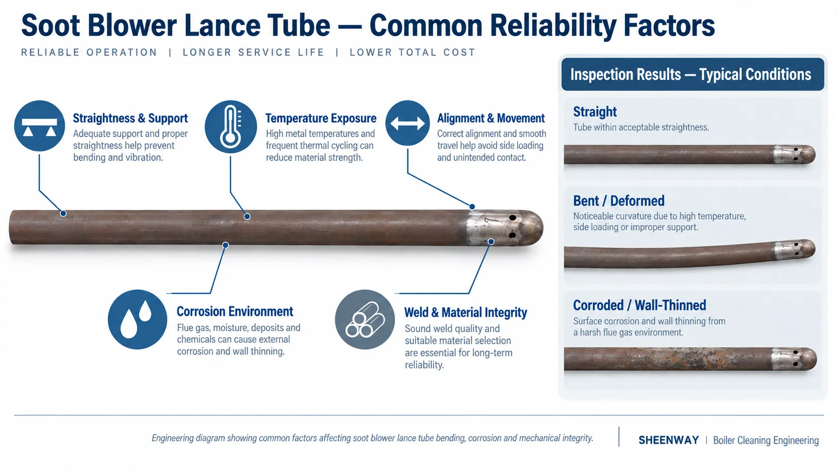
Why Soot Blower Lance Tubes Bend, Corrode or Fail
A long retractable soot blower depends on a component that looks deceptively simple:
the lance tube.
During a cleaning cycle, the lance advances into the boiler, carries the cleaning medium toward the nozzle area and moves through a high-temperature, ash-containing environment. Depending on the design, it also rotates while travelling through the target zone.
After cleaning, it retracts from the boiler.
This repeated operating cycle places the lance tube in a very different mechanical and thermal environment from an ordinary stationary pipe.
When a lance begins to bend, rub, corrode, crack or travel abnormally, the problem should therefore not automatically be blamed on the tube material alone.
Lance reliability is a system issue involving:
material + temperature + straightness + support + alignment + welding + operating conditions + maintenance.
Understanding these factors helps distinguish normal elastic deflection from actual damage—and helps avoid replacing a tube without identifying the cause of the failure.
First: Deflection Is Not the Same as Permanent Bending
A long lance tube has considerable length relative to its diameter.
When it extends into a boiler, part of the tube may behave mechanically like a long projecting structural member. Its own weight and support arrangement therefore influence its position.
Some elastic deflection under load does not automatically mean that the tube has permanently failed.
The more important distinction is whether the tube returns to its intended geometry after the load is removed, or whether it has developed permanent deformation.
EPRI's sootblower maintenance guidance notes that lance and feed-tube supports can be used to prevent deformation, with the need for such support depending on factors including travel length, lance diameter and the particular system arrangement.
SHEENWAY's own straightness-control procedure follows the same mechanical principle. Long tubes are supported during inspection so that they remain stable while rotating, while the support arrangement is intended to minimize apparent self-weight deflection that could distort the straightness assessment.
This distinction matters during inspection:
natural elastic deflection should not be confused with manufacturing or service-induced permanent bending.
1. Manufacturing Straightness Is the Starting Point
Lance reliability begins before the component is installed.
A long tube can be affected by:
- forming and machining,
- welding,
- heat treatment,
- local heating,
- handling,
- lifting,
- transport,
- and inadequate support during storage.
For long components, even relatively small dimensional deviations can become important when the tube must travel through wall-box interfaces, supports and mechanical guides.
SHEENWAY's project-specific quality-control procedure therefore identifies straightness as a controlled inspection characteristic for long feed tubes and lance tubes.
The procedure is intended specifically to prevent permanent bending or deformation during production, welding, heat treatment and handling. Tubes are supported on a straightening machine, rotated, observed relative to positioning references and corrected and re-inspected where necessary.
The associated inspection plan also requires straightness verification at production stages and final inspection.
The engineering lesson is straightforward:
straightness is not merely an appearance requirement. It is a functional dimension.
2. Support Conditions Affect Mechanical Loading
As stroke increases, the structural behavior of the lance becomes increasingly important.
The lance has to move accurately through the soot blower structure and boiler penetration while carrying its own weight.
For this reason, SHEENWAY's current long-retractable soot blower documentation identifies support as one of the items that must be confirmed during project selection, together with stroke, speed, temperature, nozzle arrangement and maintenance clearance.
Poor or damaged support can change the way loads are distributed along a long tube.
Potential consequences can include increased deflection, abnormal contact, additional resistance during travel and greater stress on local components.
This is also why a bent lance should not automatically be replaced without checking the surrounding support system.
If the underlying alignment or support problem remains, a new tube may be exposed to the same loading condition.
3. Temperature Changes Material Strength
A soot blower lance does not remain at one constant temperature.
It moves from the external boiler environment into a much hotter flue-gas space and then retracts again.
During this cycle, temperature influences both thermal expansion and the mechanical strength of the lance material.
High-temperature sootblower literature shows why this matters.
A published failure investigation of a cast stainless-steel sootblower nozzle found microstructural evidence consistent with exposure beyond its specified operating temperature, associated with premature brittle failure.
TAPPI literature on recovery-boiler soot blowers also notes that cleaning steam performs a cooling role while the nozzle end is exposed to the hot boiler environment.
The exact thermal design is application-specific, so this should not be converted into one universal temperature or minimum-flow rule.
The broader principle is:
material selection must be evaluated at the actual service temperature—not only at room-temperature strength.
This is one reason SHEENWAY determines long-retractable soot blower configuration from actual boiler flue-gas temperature and operating conditions rather than assigning identical parameters to every application.
4. Alignment Matters During Both Installation and Operation
A lance that is straight in the workshop can still experience problems after installation if the soot blower, boiler penetration, supports or surrounding structure are not correctly aligned.
Boilers also expand as operating temperature increases.
The National Board of Boiler and Pressure Vessel Inspectors specifically emphasizes that sootblower alignment should account for the thermal expansion of both the boiler and the sootblower lance.
Its guidance is primarily concerned with avoiding incorrect steam-jet impingement on boiler tubes, but the same observation highlights an important installation reality:
cold alignment and hot operating geometry are not necessarily identical.
Potential warning signs of a mechanical alignment problem can include:
- unusual rubbing,
- abnormal carriage load,
- irregular travel,
- repeated contact marks,
- difficulty entering or retracting through the wall interface,
- or repeated deformation after replacement.
These symptoms should trigger inspection of the complete mechanical path rather than the lance alone.
5. Corrosion Is Highly Dependent on the Boiler Environment
“Lance corrosion” is not one single failure mechanism.
The chemistry depends on the boiler type, fuel, ash composition, temperature and whether corrosive material can enter or remain inside the lance.
A particularly well-documented example comes from kraft recovery boilers.
A TAPPI Journal investigation reported severe internal corrosion in retractable sootblower lances where boiler flue gas entered the lance during idle periods. Under the specific chemical conditions of those recovery boilers, acidic condensate formed inside the lance and attacked the material.
Restoring and improving the low-pressure purge-air system helped prevent flue-gas infiltration and addressed the problem.
This is useful evidence, but its limits are important.
It does not prove that purge-air failure is the cause of every corroded lance in coal, biomass, waste-to-energy or other industrial boilers.
Instead, it demonstrates a broader troubleshooting principle:
when corrosion is found, identify how the corrosive environment reached that location before selecting a replacement material.
Simply choosing a nominally “more corrosion-resistant” alloy may not solve the problem if the environmental cause remains.
6. Pitting Can Become a Crack Initiation Site
Localized corrosion is particularly important because it can create stress concentrations.
A 2020 peer-reviewed failure investigation examined a stainless-steel sootblower lance/nozzle that experienced stress-corrosion cracking.
The researchers reported pitting in the failed region and identified chloride- and sulfur-containing species associated with the corrosive environment, together with thermal stresses from repeated high- and low-temperature exposure.
Again, this was one specific failure case—not a universal mechanism.
But it shows why a small pit should not always be judged only by how much surface area it occupies.
Localized attack can interact with stress.
When cracks, deep pitting or significant wall loss are suspected, visual inspection alone may no longer be sufficient.
7. Weld Integrity Is Part of Lance Integrity
Long lance assemblies can include welded joints, material transitions, flanges and nozzle-related welds depending on the design.
These regions require appropriate manufacturing and inspection controls.
The 2021 TAPPI technical paper on recovery-boiler sootblower lances documented failure mechanisms involving both a rear flange weld and manufacturing discontinuities near nozzle welds. The paper emphasizes the role of appropriate NDT in evaluating critical regions.
SHEENWAY's own project ITP similarly includes radiographic examination of applicable circumferential welds, heat-treatment records, dimensional inspection and verification of nozzle configuration and blowing angle.
This provides an important distinction:
A lance tube is not merely a length of alloy pipe.
Its reliability also depends on the quality of the completed assembly.
8. Material Grade Alone Does Not Determine Service Life
When a lance fails, it is tempting to ask:
“Should we simply use a higher-grade material?”
Sometimes material selection is part of the answer.
But material designation alone does not define reliability.
The engineer also needs to know:
- actual operating temperature,
- duration of exposure,
- tube dimensions,
- mechanical loading,
- corrosion environment,
- weld configuration,
- cleaning medium,
- support arrangement,
- and expected operating cycle.
This can be seen even within real sootblower projects.
SHEENWAY project documentation has used different approved materials for different lance and feed-tube applications, including T91, Cr18Ni9/S30408 and 15CrMo/15CrMoG depending on the specific component and purchaser requirement.
These examples should not be interpreted as a universal material-selection table.
They demonstrate the opposite:
material must be matched to the specific component and project conditions.
What Should Be Inspected on a Suspect Lance Tube?
A useful inspection begins by identifying the failure mode rather than immediately assuming replacement is necessary.
Typical areas for engineering review include:
| Inspection Area | What Engineers Are Looking For |
|---|---|
| Straightness | Permanent bending, local deformation or abnormal runout |
| Surface condition | Corrosion, pitting, erosion, scoring or overheating evidence |
| Wall thickness | Local or general material loss |
| Welds | Cracking, incomplete integrity or other relevant discontinuities |
| Nozzle area | Damage, deformation, cracking or abnormal wear |
| Support system | Worn, damaged or incorrectly positioned supports |
| Alignment | Mechanical path through carriage, wall box and boiler interface |
| Travel behavior | Abnormal resistance, vibration, rubbing or incomplete retraction |
| Operating conditions | Temperature, cleaning medium and abnormal exposure history |
The required inspection method depends on the suspected damage.
For example, the TAPPI study on recovery-boiler lances recommends volumetric NDT for certain internal corrosion mechanisms and discusses both radiographic and ultrasonic methods, noting specific limitations of UT around some austenitic and dissimilar-metal welds.
Those recommendations should not be converted into a universal NDT procedure for every soot blower.
The appropriate examination should follow the actual lance construction, materials, applicable code or specification and qualified NDT procedure.
When Should a Lance Tube Be Replaced?
There is no universal wall-thickness number, straightness value or service-hour limit that can safely determine replacement for every sootblower design.
Replacement should be based on the approved drawing, OEM or engineering acceptance criteria and the actual damage mechanism.
Conditions that normally require technical evaluation include:
Permanent deformation
The lance no longer satisfies applicable straightness or dimensional requirements.
Significant wall loss or localized corrosion
Remaining integrity must be evaluated against the required service condition.
Cracking
Especially around welds, transitions or highly stressed regions.
Nozzle or tip damage
Where geometry or structural integrity has been compromised.
Repeated travel or alignment problems
Particularly where the same problem returns after adjustment or repair.
Evidence of overheating
Material condition may need further evaluation rather than visual straightening alone.
The important point is that “straightening the tube” and “solving the failure” are not necessarily the same thing.
If permanent bending was produced by overheating, poor support or misalignment, correcting only the shape does not remove the root cause.
Replacement Projects Need More Than Length and Diameter
When purchasing a replacement sootblower lance, outside diameter and total length are important—but they are not enough.
The technical confirmation should consider, where applicable:
- lance and feed-tube dimensions,
- material specification,
- wall thickness,
- nozzle position and configuration,
- blowing angle,
- flange and interface dimensions,
- weld and heat-treatment requirements,
- operating temperature,
- cleaning medium,
- support arrangement,
- stroke and movement,
- and compatibility with the existing sootblower.
SHEENWAY's manufacturing documentation reflects this approach by combining material traceability, dimensional checks, weld inspection, straightness verification and final nozzle configuration checks rather than treating the lance simply as a piece of pipe.
For retrofit and spare-part projects, this is particularly important.
A tube that physically fits into the machine is not necessarily technically equivalent to the original component.
Conclusion
Soot blower lance-tube failures rarely have only one possible cause.
Permanent bending may involve manufacturing straightness, mechanical support, alignment or temperature.
Corrosion depends on the actual chemical environment and the path by which corrosive material reaches the lance.
Cracking can involve corrosion, thermal cycling, stress concentration, weld quality or combinations of these mechanisms.
For this reason, an effective investigation should move beyond the question:
“What material is this tube made from?”
and instead ask:
What mechanical, thermal and chemical conditions has this lance actually experienced?
SHEENWAY controls long-tube manufacturing through material verification, straightness inspection, dimensional checks and relevant weld-quality controls, while long-retractable soot blower parameters are configured around the actual boiler and project conditions.
For operators and maintenance teams, the same system-level approach is appropriate in service:
inspect the damage, identify the mechanism, correct the cause, and then determine whether repair or replacement is technically justified.
More from Sheenway
Continue Reading
Retractable Boiler Temperature Probe: Why It Matters During Boiler Startup
During boiler startup, furnace exit gas temperatures can rise before sufficient steam cooling is established in certain heating surfaces. A retractable boiler temperature probe positions a thermocouple in the gas path to provide temperature information for operating decisions. This guide explains the working principle, startup applications, measurement limitations and selection requirements of the SHEENWAY SW-MTPS.
Read articleRake-Type Soot Blower Design for SCR: Nozzle Layout, Travel and Support
Rake-type soot blowers use non-rotating, axially moving cleaning assemblies to direct steam or compressed air toward SCR catalysts and other structured surfaces. This guide explains nozzle layout, travel, support and guide arrangements, cleaning-medium conditions and the engineering checks required before selecting or replacing a rake-type soot blower.
Read articleMulti-Medium Retractable Soot Blowers: When Steam Alone Is Not Enough
Steam soot blowing is effective for many boiler cleaning applications, but certain gypsum, salt and strongly bonded deposits may require additional cleaning methods. This guide explains how multi-medium retractable soot blowers combine different cleaning options, when water washing may be considered, and how engineers select an appropriate solution for gas-gas heaters and air preheaters.
Read article