
Recovery Boiler Soot Blower Retrofit: 14 Long Retractable Units with Dual-Medium Positive-Pressure Protection
A targeted retrofit of 14 SW-SLRM long retractable soot blowers within a two-boiler recovery system, featuring 4.48 m stroke, dual-medium positive-pressure wall-box protection, existing-interface compatibility and integration with the plant's existing control system.
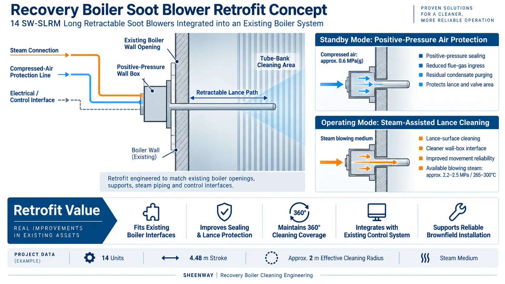
Retrofitting an existing recovery boiler is fundamentally different from designing a soot blowing system for a new boiler.
The new equipment must not only meet the required cleaning performance. It must also fit the existing boiler openings, steam connections, structural interfaces and control architecture while improving reliability under the demanding deposit and flue-gas conditions of recovery-boiler service.
In this project, SHEENWAY carried out a targeted replacement of 14 long retractable soot blowers within an existing two-boiler recovery system at a pulp and paper manufacturing facility in southwest China.
Each recovery boiler had a solids processing capacity of approximately 250 tDS/d and was originally equipped with 20 long retractable soot blowers used for cleaning deposits from the superheater, evaporative heating surfaces and economizer sections.
The retrofit focused on replacing selected existing units while retaining compatibility with the established boiler and plant systems.
Project Overview
The project included 14 SW-SLRM Long Retractable Soot Blowers with a project-specific stroke of approximately:
4.48 meters
The soot blowers were designed for:
- 360° blowing coverage
- Approximately 2 m effective cleaning radius
- 9–35 r/min rotational speed
- 0.9–3.5 m/min forward and reverse travel
- Steam as the blowing medium
The available soot blowing steam conditions were approximately:
2.2–2.5 MPa / 265–300°C
The project also had access to dry compressed air at approximately 0.6 MPa(g) for auxiliary and positive-pressure protection functions.
The engineering scope covered not only the soot blower body, but also wall-box sealing, cleaning connections, valves, electrical interfaces, local controls, existing control-system integration, dismantling, installation and commissioning.
The Retrofit Challenge: New Equipment Within an Existing Boiler System
One of the central requirements of this project was compatibility.
This was not a new-build installation where boiler openings, platforms, piping and controls could be designed around new soot blowers.
The new equipment had to be installed within an operating recovery-boiler system that already had established:
- Boiler-wall openings
- Soot blower mounting positions
- Steam piping
- Local structural supports
- Electrical connections
- Control interfaces
This meant dimensional confirmation and interface engineering were critical.
A replacement soot blower can be mechanically reliable on its own and still create problems if its centerline, wall-box position, steam inlet, travel geometry or control signals do not correctly match the existing installation.
The retrofit was therefore engineered around the actual site arrangement rather than treating the replacement as a simple catalogue-equipment substitution.
Why SW-SLRM Long Retractable Soot Blowers Were Used
The project utilized SW-SLRM Long Retractable Soot Blowers with an approximately 4.48 m stroke.
The current SW-SLRM series is designed for long retractable applications with strokes up to 7.60 m and is typically used for cleaning boiler heating surfaces such as superheaters, reheaters and economizers.
During operation, the lance rotates while travelling into the boiler so that the steam jets follow the required cleaning trajectory across the heating surface.
After the blowing cycle, the lance retracts from the boiler.
This operating principle is particularly suitable for recovery-boiler applications because the lance is exposed to the internal boiler environment only during the required cleaning period rather than remaining continuously inside the gas path.
For this project, the equipment was configured around the existing 4.48 m installation geometry while maintaining the required 360° cleaning coverage.
A Different Wall-Box Strategy: Sealing and Cleaning
One of the most technically distinctive aspects of this retrofit was the wall-box and cleaning arrangement.
The project required a positive-pressure wall box with both sealing and cleaning functions.
Rather than treating the wall box simply as a mechanical penetration between the soot blower and boiler casing, the design used different media under different operating conditions.
During Standby: Compressed-Air Protection
When the soot blower was not using steam, dry compressed air could be introduced into the positive-pressure wall-box system.
The air served several purposes.
It helped maintain positive pressure around the boiler penetration, reducing the possibility of furnace gas entering the soot blower lance and valve areas.
Air could also be introduced through the soot blower cleaning path toward the lance and nozzle region.
This helps:
- Reduce flue-gas backflow into the soot blower
- Protect valve and lance components from the furnace atmosphere
- Maintain positive pressure around the nozzle area
- Remove residual condensate from the lance after steam blowing
- Improve conditions inside the soot blower during standby
For a recovery boiler, where the furnace environment may contain corrosive and deposit-forming constituents, preventing uncontrolled gas ingress is an important part of long-term equipment protection.
During Operation: Steam Cleaning of the Lance Surface
When the soot blower entered a steam blowing cycle, the cleaning function changed.
Steam could be introduced through the dedicated cleaning arrangement in the wall-box area to help clean the external surface of the moving lance tube.
This is important because a soot blower lance does not operate in isolation from its environment.
Deposits accumulating around the lance and boiler penetration can gradually interfere with sealing and mechanical movement.
The wall-box design therefore created a system in which:
compressed air provides positive-pressure protection during standby, while steam supports lance-surface cleaning during soot blowing.
This dual-medium strategy is one of the strongest engineering features of the project.
Protection Against Flue-Gas Ingress and Corrosion
The project documentation placed particular emphasis on preventing furnace gas from flowing backward into soot blower components.
Uncontrolled flue-gas ingress can expose internal lance, valve and sealing components to an environment they were not intended to experience continuously.
The positive-pressure arrangement therefore works as part of a broader protection strategy.
Instead of relying only on mechanical contact seals, the system uses pressure differential and cleaning media to create a more controlled interface between the recovery boiler and the soot blower.
This helps support:
- Internal component protection
- Wall-box sealing
- Cleaner lance operation
- Reduced deposit migration
- Long-term maintainability
Materials Selected for Recovery-Boiler Service
The project also established material requirements for components exposed to elevated temperature and the recovery-boiler environment.
High-temperature and corrosion-resistant materials were specified for critical components such as the inner tube, lance assembly and related parts.
The final material configuration was selected to satisfy the operating environment while maintaining sufficient strength, wear resistance and dimensional stability.
For a retractable soot blower, material selection must account for a combination of:
- Steam conditions
- Flue-gas exposure
- Thermal cycling
- Mechanical travel
- Rotational loading
- Deposit environment
These requirements are particularly relevant where the same lance repeatedly enters and leaves the boiler over a long service period.
Reliable Mechanical Travel
Smooth lance movement was another major design requirement.
The project specified reliable guide, carriage and drive arrangements so that the lance could maintain correct alignment during both forward and reverse travel.
The soot blower design also incorporated lubrication and sealing provisions for moving components.
Forward and reverse travel, rotation, valve operation and travel-limit signals must work as a coordinated sequence.
If any one of these functions becomes inconsistent, the result may be abnormal lance movement, incomplete retraction or unnecessary maintenance.
For this reason, the retrofit was evaluated as a complete electromechanical operating sequence rather than simply as a mechanical replacement.
Helical Phase Control for Heating-Surface Protection
The soot blowers incorporated a phase-change mechanism intended to prevent steam jets from repeatedly following exactly the same trajectory during every blowing cycle.
Changing the relative phase of successive cleaning paths helps distribute the steam-jet impact across the heating surface.
The purpose is not to reduce cleaning effectiveness.
It is to balance:
deposit removal and long-term tube protection.
This is an important principle in soot blowing engineering because repeatedly concentrating a high-energy jet on the same tube position can increase localized erosion risk.
Integration with the Existing Control System
Another important characteristic of the project was that the existing plant control architecture was retained.
The 14 replacement soot blowers were connected to the plant's existing control system and commissioned together with the owner's controls.
Local functions included commands such as:
- Local / remote selection
- Forward
- Reverse
- Start
- Stop
- Travel and status feedback
The existing soot blowing arrangement therefore did not need to be completely rebuilt simply because the mechanical equipment was replaced.
This reduces unnecessary system changes and is particularly valuable in brownfield industrial projects where the original DCS or PLC architecture remains serviceable.
The original project documentation also includes the existing soot blower control-layout screens, illustrating the control environment into which the replacement equipment had to be integrated.
Installation and Brownfield Execution
The project included dismantling of the existing soot blowers, installation of the replacement equipment and joint commissioning.
Existing units were removed from their original installation points, while the new soot blowers were positioned and aligned to match the established boiler arrangement.
This required attention to:
- Installation centerline
- Existing boiler openings
- Wall-box alignment
- Steam connections
- Electrical interfaces
- Structural support
- Travel clearance
For retrofit projects, these details are often as important as the equipment specification itself.
A technically suitable soot blower must also be practically installable within the dimensional constraints of an existing plant.
Cold and Hot Commissioning
After installation, the replacement equipment was checked through cold and hot commissioning.
Cold checks focused on functions such as:
- Manual and motor-driven travel
- Forward and reverse movement
- Valve operation
- Limit-switch response
- Electrical control
- Equipment alignment
Hot commissioning then verified equipment performance under actual boiler operating conditions, including steam operation, lance movement, valve response, sealing and interaction with the existing control system.
This staged commissioning approach allows mechanical, electrical and operating issues to be identified before the equipment enters normal service.
Why This Project Matters
This project is a good example of a type of work that is common in industrial plants but technically different from both a new-build project and a complete boiler-wide modernization.
The objective was not to redesign the entire recovery boiler.
It was to replace selected existing soot blowers while improving the reliability and protection of the new equipment and maintaining compatibility with the established boiler system.
The project therefore required coordination between:
14 replacement soot blowers
4.48 m existing installation geometry
positive-pressure wall boxes
compressed-air sealing and protection
steam lance-surface cleaning
existing steam interfaces
existing electrical and control architecture
on-site installation and commissioning
This type of brownfield retrofit demonstrates a different engineering capability from simply supplying equipment for a new boiler.
For SHEENWAY, a successful replacement project means that the new equipment must not only work correctly — it must also work correctly with everything that is already there.
SHEENWAY Recovery Boiler Retrofit Solutions
SHEENWAY provides equipment replacement and retrofit engineering for recovery boilers and pulp and paper plants, including SW-SLRM long retractable soot blowers, wall-box systems, positive-pressure sealing, sealing and cleaning air, replacement parts, interface engineering, control-system integration and installation/commissioning support.
For an existing soot blower replacement project, our engineering team can evaluate original installation dimensions, boiler interfaces, steam conditions, control signals, operating environment and maintenance requirements before determining the final replacement configuration.
Planning to replace aging soot blowers without rebuilding the entire boiler cleaning system? Contact SHEENWAY to discuss your existing installation and retrofit requirements.
More from Sheenway
Continue Reading
Retractable Boiler Temperature Probe: Why It Matters During Boiler Startup
During boiler startup, furnace exit gas temperatures can rise before sufficient steam cooling is established in certain heating surfaces. A retractable boiler temperature probe positions a thermocouple in the gas path to provide temperature information for operating decisions. This guide explains the working principle, startup applications, measurement limitations and selection requirements of the SHEENWAY SW-MTPS.
Read articleRake-Type Soot Blower Design for SCR: Nozzle Layout, Travel and Support
Rake-type soot blowers use non-rotating, axially moving cleaning assemblies to direct steam or compressed air toward SCR catalysts and other structured surfaces. This guide explains nozzle layout, travel, support and guide arrangements, cleaning-medium conditions and the engineering checks required before selecting or replacing a rake-type soot blower.
Read articleMulti-Medium Retractable Soot Blowers: When Steam Alone Is Not Enough
Steam soot blowing is effective for many boiler cleaning applications, but certain gypsum, salt and strongly bonded deposits may require additional cleaning methods. This guide explains how multi-medium retractable soot blowers combine different cleaning options, when water washing may be considered, and how engineers select an appropriate solution for gas-gas heaters and air preheaters.
Read article