
Rake-Type Soot Blower Design for SCR: Nozzle Layout, Travel and Support
Rake-type soot blowers use non-rotating, axially moving cleaning assemblies to direct steam or compressed air toward SCR catalysts and other structured surfaces. This guide explains nozzle layout, travel, support and guide arrangements, cleaning-medium conditions and the engineering checks required before selecting or replacing a rake-type soot blower.
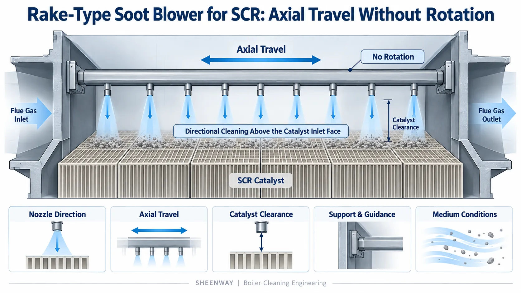
A rake-type soot blower is designed for industrial cleaning applications where the direction of the cleaning jet is as important as the movement of the cleaning equipment.
This requirement is particularly relevant to selective catalytic reduction (SCR) systems, where flue gas passes through structured catalyst channels.
Unlike conventional boiler tube banks, SCR catalyst modules contain organized flow passages that must remain accessible to the flue gas.
A cleaning system must therefore direct sufficient energy toward the appropriate catalyst surfaces without introducing unnecessary mechanical stress.
This is one reason rake-type soot blowers use a non-rotating cleaning assembly combined with axial travel.
For equipment selection, however, identifying a non-rotating lance is only the beginning.
Nozzle orientation, movement stroke, support and guidance, cleaning-medium conditions and installation geometry must also be considered.
This guide examines the engineering design of rake-type soot blowers, with reference to the SHEENWAY SW-SRKS.
1. What Is a Rake-Type Soot Blower?
A rake-type soot blower is a retractable cleaning device that uses a specially configured blowing assembly to direct steam or compressed air toward a designated cleaning surface.
Its defining characteristics are:
- axial movement of the blowing assembly;
- a non-rotating rake or lance arrangement;
- nozzles oriented toward the required cleaning region;
- and a support and guiding system appropriate to the cleaning geometry.
The design is different from a conventional long retractable soot blower.
A long retractable soot blower commonly combines axial movement and lance rotation to distribute cleaning jets throughout a boiler tube bank.
A rake-type soot blower instead maintains the selected nozzle orientation while moving the rake through its required travel.
Babcock & Wilcox describes straight-line retractable soot blowers with rake-type cleaning assemblies for applications where lance rotation is undesirable or unnecessary.
Clyde Industries similarly uses a non-rotating rake arrangement for SCR and other structured heating surfaces.
The fundamental design concept is therefore:
Controlled Axial Travel + Fixed Nozzle Orientation = Directional Cleaning Coverage
2. Why SCR Catalyst Geometry Matters
SCR systems are used to reduce nitrogen oxide emissions from industrial flue gas.
Within the SCR reactor, the flue gas passes through catalyst modules that provide surfaces for the intended chemical reactions.
Catalyst modules are constructed with defined flow passages.
These passages can be affected by fly ash and other particulate deposits.
If deposits accumulate near the channel entrances or within accessible portions of the passages, gas flow may become restricted.
This can contribute to increased reactor pressure drop and reduced effective catalyst utilization.
The cleaning requirement is different from removing ash from the external surfaces of large boiler tubes.
For SCR applications, cleaning energy must be directed toward the relevant catalyst openings and deposit locations.
Babcock & Wilcox specifically identifies directed steam or air cleaning as a common approach for SCR catalyst assemblies.
The required cleaning intensity must also respect the mechanical characteristics of the catalyst substrate.
This combination of directional coverage and controlled cleaning action makes SCR a suitable application to evaluate rake-type soot blowing.
3. Why the Rake Does Not Rotate
In a long retractable soot blower, lance rotation helps distribute cleaning jets around the lance as it travels.
This is useful when the target consists of tube banks extending around the cleaning path.
For a catalyst module, however, the desired cleaning direction may be much more specific.
The objective may be to maintain the jet orientation toward a defined catalyst face throughout the cleaning movement.
A rotating lance could direct the jet away from the intended target during part of its rotation.
A non-rotating rake avoids this unnecessary change in angular orientation.
The rake moves axially, while its nozzles maintain their designed direction relative to the cleaning assembly.
This helps create a more controlled cleaning pattern for structured target surfaces.
However, non-rotating does not mean the soot blower is stationary.
The rake still requires mechanical travel to move its nozzles across the intended cleaning zone.
The design combines movement in one direction with controlled nozzle orientation rather than using rotational movement to generate coverage.
4. How Axial Travel Creates Cleaning Coverage
The movement stroke of a rake-type soot blower is an important part of its cleaning geometry.
During operation, the assembly travels through the designated cleaning region according to the equipment's approved operating sequence.
The axial movement changes the position of the nozzles relative to the catalyst modules or other target surfaces.
When the rake reaches its specified travel limit, it returns according to the control arrangement.
The resulting coverage depends on several factors:
Travel distance
How far the blowing assembly moves relative to the target surface.
Nozzle distribution
How the nozzles are arranged along the rake.
Nozzle orientation
Where the cleaning jets are directed during movement.
Target geometry
The dimensions and arrangement of the catalyst modules or heating surfaces.
Cleaning-medium conditions
The available jet action at the actual cleaning distance.
This means that stroke alone cannot define the cleaning coverage.
A long stroke with an unsuitable nozzle configuration may still leave areas insufficiently cleaned.
Conversely, a correctly arranged rake may achieve the required coverage without reproducing the travel and rotation pattern of a conventional soot blower.
For SHEENWAY SW-SRKS, the stroke and movement speed are determined according to the project requirements.
5. Nozzle Layout Is More Than Nozzle Quantity
The nozzle arrangement is one of the most important aspects of rake-type soot blower design.
A technical review should not focus only on the number of nozzle openings.
It should also consider:
- nozzle diameter and geometry;
- axial spacing;
- angular orientation;
- distance to the target surface;
- overlap between adjacent cleaning regions;
- and the mechanical limits of the target equipment.
For SCR applications, the nozzle configuration must be evaluated against the actual catalyst arrangement.
If the jet direction does not correspond to the desired cleaning region, increasing the number of nozzles may not solve the underlying problem.
Likewise, a high nominal blowing pressure does not establish whether the jet reaches the appropriate catalyst area at a suitable intensity.
The effective cleaning action is related to the nozzle outlet conditions, jet propagation and the distance to the catalyst surface.
Nozzle layout should therefore be engineered from the required cleaning coverage, not selected from a fixed universal pattern.
SHEENWAY's SW-SRKS documentation specifies that nozzle quantity and diameter are determined according to the project.
6. Catalyst Protection: Why More Cleaning Force Is Not Always Better
SCR catalyst cleaning introduces an important mechanical constraint.
Catalyst substrates may be more susceptible to mechanical damage than conventional boiler pressure-part tubes.
For this reason, cleaning should not be designed simply around maximizing jet impact.
Babcock & Wilcox notes that steam used for SCR catalyst cleaning is generally applied at a lower jet velocity than in conventional boiler soot-blowing applications, helping reduce the risk of mechanical or erosive damage.
Moisture in the steam can create additional risks for some catalyst designs, including erosion or thermal shock.
The distinction between supply pressure and jet impact is especially important.
A soot blower may have a specified operating pressure at its supply or valve system.
That number is not identical to the pressure or mechanical action experienced at the catalyst surface.
The actual cleaning effect depends on the nozzle design, flow, distance and operating arrangement.
SHEENWAY's SW-SRKS documentation lists approximately 1.5 MPa as a reference blowing pressure.
This is a product reference value.
It must not be interpreted as a universally appropriate catalyst-cleaning pressure or as a direct measurement of impact on the catalyst.
Final conditions must be confirmed against the project and catalyst requirements.
7. Why Rake Support and Guidance Matter
A non-rotating rake still needs reliable mechanical guidance.
The blowing assembly may travel across a relatively wide cleaning region while operating in a hot, ash-laden gas environment.
Its geometry must remain sufficiently stable to preserve the intended nozzle orientation and clearances.
Potential engineering concerns include:
Mechanical alignment
The rake must follow its specified travel path.
Support arrangement
The assembly must have appropriate support for its length, weight and loading.
Guiding components
The guidance system must maintain the required movement geometry.
Thermal conditions
Operating temperature and thermal expansion may affect alignment and clearance.
Maintenance accessibility
Components should be accessible for inspection and replacement under the applicable maintenance procedure.
SHEENWAY's SW-SRKS documentation identifies a front support, support and guide pipes, and a non-rotating rake assembly among the relevant components.
These features distinguish its cleaning assembly from that of a conventional rotating long retractable soot blower.
The specific support arrangement must be confirmed for each installation.
8. Mechanical and Control Systems
Although the rake arrangement differs from a conventional rotating lance, the SW-SRKS shares some general mechanical and operating principles with retractable soot blowers.
Its documented components include:
- carriage, motor and reducer;
- beam structure;
- lift valve and connection components;
- feed tube;
- wall box;
- rake and main pipe assembly;
- support and guide components;
- electrical control equipment;
- and travel limit switches.
These components must work together to provide the required cleaning movement and medium supply.
For a replacement or retrofit project, the engineer should confirm the actual mechanical interfaces and control sequence.
The existing machine should not be considered interchangeable with a conventional long retractable soot blower simply because some drive or control elements are similar.
The different cleaning assembly and directional requirements are fundamental to the application.
9. Rake-Type vs Long Retractable vs Fixed Rotary
Three soot blower types may use steam or compressed air while applying fundamentally different motion principles.
| Engineering Factor | Rake-Type Soot Blower | Long Retractable Soot Blower | Fixed Rotary Soot Blower |
|---|---|---|---|
| Axial movement | Yes | Yes | No long axial travel |
| Lance rotation | No | Typically yes | Yes |
| Main coverage mechanism | Fixed nozzle orientation combined with axial travel | Nozzle movement combined with travel and rotation | Fixed-position rotary jet movement |
| Typical applications | SCR catalysts and selected structured surfaces | Deep boiler convection tube banks | Selected heating surfaces accessible from a fixed position |
| Key selection factors | Nozzle direction, stroke, support, target geometry | Stroke, rotation, nozzle geometry, tube-bank depth | Cleaning arc, element exposure, support |
| Main design objective | Directional cleaning coverage | Distributed coverage inside tube banks | Rotary coverage without long insertion travel |
This comparison does not establish that one type is universally superior.
The correct design depends on the shape of the target surface, its operating environment and the cleaning mechanism required.
10. SHEENWAY SW-SRKS Reference Specifications
The SW-SRKS Rake-Type Soot Blower is intended primarily for SCR catalyst-cleaning applications.
Depending on the project and operating conditions, the rake-type arrangement may also be evaluated for selected finned economizers, tubular air heaters and other structured heating surfaces where directional cleaning is required.
The current SHEENWAY documentation lists the following reference parameters.
| Parameter | SW-SRKS Reference |
|---|---|
| Product type | Rake-Type Retractable Soot Blower |
| Primary application | SCR catalyst cleaning |
| Cleaning medium | Steam or compressed air |
| Rake movement | Axial travel without rake rotation |
| Stroke | Project-specific |
| Travel speed | Project-specific |
| Reference blowing pressure | Approx. 1.5 MPa |
| Reference effective blowing distance | Approx. 1.5 m |
| Installation-area flue-gas temperature limit in current specification | 600°C |
| Nozzle quantity and diameter | Project-specific |
| Reference domestic motor | Y90S-4 B5, 1.1 kW, 1400 r/min, 380 V, 50 Hz, three-phase |
These figures are reference product specifications, not universal operating recommendations.
The 600°C figure is a stated limit in the current SW-SRKS product information and should not be generalized to other manufacturers or different rake-type designs.
Likewise, effective blowing distance and nominal supply pressure do not independently establish cleaning performance or catalyst safety.
The final configuration must be confirmed against the catalyst supplier's requirements, operating conditions and approved project specifications.
11. What Should Be Confirmed Before Selection?
A rake-type soot blower should be selected from the target equipment's actual geometry and cleaning requirements.
| Required Information | Engineering Purpose |
|---|---|
| SCR reactor or equipment model | Establishes application and equipment configuration |
| Catalyst type and module arrangement | Defines target cleaning geometry |
| Catalyst face dimensions and orientation | Supports nozzle layout and required travel |
| Deposit type and location | Identifies cleaning objective |
| Flue-gas temperature | Supports material and operating-condition review |
| Permitted catalyst cleaning conditions | Defines mechanical and thermal limits |
| Available steam or compressed air | Establishes supply pressure, flow and medium quality |
| Nozzle-to-target distance | Supports jet action and coverage review |
| Required stroke and movement speed | Defines movement requirements |
| Rake support and guiding conditions | Supports mechanical stability and clearance |
| Wall-box and mounting interfaces | Supports installation compatibility |
| Electrical control and limit switches | Supports movement sequencing and protection |
For existing equipment, original drawings and site photographs can be useful.
However, a general drawing or machine model alone should not be treated as sufficient evidence of complete compatibility.
Each replacement must be reviewed against the actual installed arrangement.
12. Common Mistakes in Rake-Type Soot Blower Selection
Several mistakes can compromise the suitability of a proposed cleaning arrangement.
Treating the rake as a rotating lance
A rake-type design depends on maintaining the intended directional orientation.
Selecting the machine only by stroke
Stroke matters, but nozzle distribution and target geometry are equally important.
Assuming higher blowing pressure always improves cleaning
For catalysts, inappropriate jet action can increase the risk of damage.
Ignoring support and alignment
Poor guidance can alter the relationship between nozzle position and the intended cleaning area.
Copying another installation without verifying conditions
Different SCR reactors can have different module dimensions, catalyst arrangements and permitted cleaning conditions.
Assuming all deposits can be removed through routine soot blowing
Strongly bonded or chemically influenced deposits may require additional investigation and different treatment.
The purpose of the selection process is to establish a suitable cleaning mechanism, not simply to reproduce the dimensions of another machine.
13. How Should Performance Be Evaluated?
After installation, the rake-type soot blower should be assessed against its intended cleaning objective.
Mechanical operation alone is not sufficient evidence of cleaning performance.
Depending on the SCR system and available instrumentation, useful observations may include:
- reactor pressure-drop trends under comparable gas-flow conditions;
- deposit accumulation at catalyst inlets;
- inspection findings;
- changes in cleaning-cycle effectiveness;
- evidence of catalyst damage;
- and relevant operational observations from the SCR system.
Reactor pressure drop must be interpreted with respect to gas flow, temperature and operating conditions.
Likewise, NOx removal performance depends on several factors besides catalyst cleanliness, including temperature, reagent distribution and catalyst condition.
For this reason, improved or deteriorated SCR performance should not be attributed to soot blowing without evaluating the wider system.
Conclusion
A rake-type soot blower is not simply a long retractable soot blower with a different nozzle arrangement.
Its non-rotating rake, directional cleaning pattern, axial movement and guiding structure form a distinct mechanical cleaning concept.
For SCR catalyst applications, the critical objective is to distribute suitable cleaning energy across the required catalyst regions while respecting the mechanical limitations of the catalyst.
SHEENWAY's SW-SRKS is designed around this approach, with project-specific stroke, travel speed and nozzle configuration.
The correct selection depends on catalyst geometry, deposit characteristics, blowing-medium conditions, support and installation interfaces.
When the target surface requires directional cleaning, nozzle orientation and controlled movement matter more than simply increasing blowing pressure.
For SCR cleaning and retrofit projects, SHEENWAY can review existing equipment information, catalyst arrangement, operating conditions and replacement requirements to assess an appropriate SW-SRKS configuration.
More from Sheenway
Continue Reading
Retractable Boiler Temperature Probe: Why It Matters During Boiler Startup
During boiler startup, furnace exit gas temperatures can rise before sufficient steam cooling is established in certain heating surfaces. A retractable boiler temperature probe positions a thermocouple in the gas path to provide temperature information for operating decisions. This guide explains the working principle, startup applications, measurement limitations and selection requirements of the SHEENWAY SW-MTPS.
Read articleMulti-Medium Retractable Soot Blowers: When Steam Alone Is Not Enough
Steam soot blowing is effective for many boiler cleaning applications, but certain gypsum, salt and strongly bonded deposits may require additional cleaning methods. This guide explains how multi-medium retractable soot blowers combine different cleaning options, when water washing may be considered, and how engineers select an appropriate solution for gas-gas heaters and air preheaters.
Read articleHow to Select a Sonic Soot Blower: Frequency, Coverage and Installation Requirements
Selecting a sonic soot blower requires more than comparing frequency and acoustic output. Deposit characteristics, equipment geometry, installation distance, compressed-air supply and structural resonance all influence the effectiveness of acoustic cleaning. This guide explains the main engineering selection factors and introduces the SHEENWAY Sonic Soot Blower product range.
Read article