
Retractable Boiler Temperature Probe: Why It Matters During Boiler Startup
During boiler startup, furnace exit gas temperatures can rise before sufficient steam cooling is established in certain heating surfaces. A retractable boiler temperature probe positions a thermocouple in the gas path to provide temperature information for operating decisions. This guide explains the working principle, startup applications, measurement limitations and selection requirements of the SHEENWAY SW-MTPS.
Boiler startup is a critical operating period during which furnace temperatures, steam flow and heating-surface conditions can change rapidly.
In certain boiler configurations, high-temperature flue gas can reach superheater or reheater sections before sufficient cooling steam flow has been established.
Under these conditions, operators need reliable temperature information to assess the thermal environment around vulnerable heating surfaces.
One instrument used for this purpose is the retractable boiler temperature probe.
Unlike a conventional steam soot blower, a retractable temperature probe is not designed to remove ash deposits. Its primary function is to position a temperature sensor at a specified location in the flue-gas path and provide measurement information to the boiler operator or control system.
This article explains how retractable temperature probes work, why they are used during boiler startup, and which engineering parameters should be considered when selecting a system such as the SHEENWAY SW-MTPS Temperature Probe.
1. Why Temperature Monitoring Matters During Boiler Startup
During normal boiler operation, steam flow helps remove heat from the internal surfaces of superheater and reheater tubes.
During startup, however, the operating conditions can be different.
Fuel firing, flue-gas temperature and steam circulation do not necessarily increase at the same rate.
Depending on the boiler configuration and startup procedure, certain heating surfaces may experience significant thermal exposure before their intended cooling flow is fully established.
This can create a risk of excessive tube-metal temperature and thermal stress.
The condition is particularly relevant where reheater or superheater surfaces are exposed to hot furnace-exit gases during transitional operating periods.
Monitoring the temperature of the surrounding flue gas provides useful information for startup decisions.
For example, a rising furnace-exit gas temperature may indicate that the thermal environment is becoming more demanding.
However, flue-gas temperature is not the same as tube-metal temperature.
Tube-metal temperature also depends on heat transfer, steam flow, tube construction and other operating factors.
A temperature probe therefore provides an important monitoring input, but does not independently establish the temperature or remaining life of the nearby pressure parts.
2. What Is a Retractable Boiler Temperature Probe?
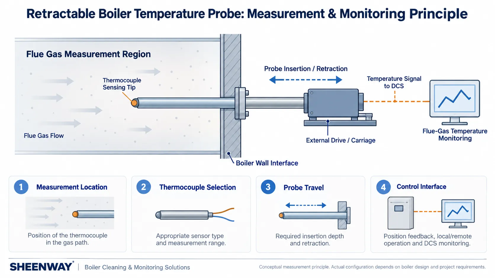
A retractable boiler temperature probe is a mechanical and instrumentation assembly designed to insert a temperature-sensing element into a defined flue-gas region.
A typical system includes a probe tube, a thermocouple, a drive mechanism, a support structure, a boiler-wall interface and the necessary electrical instrumentation.
The thermocouple is mounted near the end of the probe tube.
During operation, the drive mechanism advances the probe into the intended measurement position.
The thermocouple then provides a temperature signal that can be processed by the associated instrumentation.
When measurement at that position is no longer required, or when the approved operating procedure calls for retraction, the probe can be withdrawn.
This differs fundamentally from a soot blower.
A soot blower delivers cleaning energy to deposits. A retractable temperature probe positions a sensor to obtain temperature information.
Although the two types of equipment may share some general mechanical features, their operating functions are different.
3. How Does the SHEENWAY SW-MTPS Work?
The SHEENWAY SW-MTPS uses a motor-driven mechanical arrangement to move a thermocouple probe into and out of a specified boiler gas path.
Its working sequence can be described in four stages.
Stage 1 — Probe insertion
The drive moves the probe tube forward through the designated boiler-wall opening.
Stage 2 — Measurement positioning
The thermocouple reaches the measurement location specified for the application.
Stage 3 — Temperature monitoring
The thermocouple signal is transmitted through the associated measurement system for indication or monitoring.
Stage 4 — Probe retraction
The probe returns to its retracted position according to the operating procedure and control arrangement.
The SW-MTPS documentation identifies local operation, remote operation and DCS monitoring as supported functions.
The movement speed is approximately 2.5 m/min, while the required stroke is determined for the individual project.
Importantly, the SW-MTPS is a linear retractable measurement device.
Its normal measuring principle does not require a rotating soot-blower nozzle or a steam-cleaning jet.
4. Why Is a Retractable Design Used Instead of a Permanently Inserted Sensor?
High-temperature boiler gas paths can present challenging conditions for temperature-measuring equipment.
Depending on the location, the sensor assembly may be exposed to high temperatures, ash particles, corrosive gas constituents and changing thermal conditions.
A retractable design allows the sensing assembly to be positioned in the gas path when measurement is required and removed according to the approved operating sequence.
This arrangement may help limit unnecessary exposure compared with leaving an equivalent probe continuously inserted.
It can also provide a defined mechanical method for positioning and withdrawing the sensor.
However, retraction does not eliminate the need to consider probe material, thermal expansion, mechanical loading or sensor protection.
The actual benefit depends on the operating cycle and installation conditions.
SHEENWAY also lists a probe-tube cooling system as an optional configuration.
Whether cooling is necessary must be determined from the specified thermal conditions and approved design, rather than assumed for every installation.
5. Where Should Furnace-Exit Gas Temperature Be Measured?
The measurement location is one of the most important decisions in a retractable temperature-probe project.
A probe near the furnace exit or the entrance to a reheater section may provide information relevant to the thermal exposure of nearby heating surfaces.
However, temperature within a large boiler gas path is not necessarily uniform.
Gas temperature can vary with the position of the sensor, furnace load, combustion conditions and flue-gas distribution.
Therefore, the project must identify what the measurement is intended to represent.
Possible objectives include:
- monitoring temperature at a specified furnace-exit location;
- observing temperature trends during startup;
- evaluating conditions near a reheater or superheater inlet;
- and obtaining supplementary data during low-load operation.
The specified insertion depth must correspond to the intended measurement location.
A suitable probe length alone does not establish that the sensing element is positioned correctly.
The mounting arrangement, available travel, clearances and local thermal conditions all require verification.
6. Flue-Gas Temperature Is Not Tube-Metal Temperature
This distinction is essential when interpreting measurement data.
A thermocouple placed in a flue-gas stream responds to the thermal conditions at its sensing junction.
The nearby boiler tubes may experience different temperatures because of heat transfer through their walls and cooling by the steam or water flowing inside them.
Consequently, a gas-temperature reading must not be reported as a direct measurement of reheater or superheater tube-metal temperature.
There is also an additional measurement consideration.
Thermocouple readings in hot gas environments can be influenced by radiative heat exchange, gas velocity, sensor construction and response time.
Research published by the U.S. National Institute of Standards and Technology (NIST) has demonstrated that radiative effects and finite sensor response can introduce uncertainty in high-temperature gas measurements.
Although those studies include fire environments rather than the SW-MTPS specifically, the underlying thermocouple measurement principles are relevant.
For engineering applications, measurement uncertainty and sensor installation effects should therefore be considered.
A temperature probe supplies measured information at its sensing location; safe interpretation requires an understanding of what that measurement represents.
7. Thermocouple Selection and Measurement Range
The thermocouple is the primary sensing element in the temperature-probe assembly.
Selection should account for the temperature range, required accuracy, environmental conditions and measurement-system compatibility.
The SHEENWAY SW-MTPS documentation specifies a project-dependent measurement range and identifies a thermocouple assembly in its reference configuration.
It also provides recommended temperature-indication and signal-output arrangements.
However, the measurement range must not be determined solely from the scale printed on a display instrument.
For example, the current product documentation includes a 0–800°C indication scale as a reference instrument option.
This does not establish 800°C as the universal maximum measurement capability of every SW-MTPS installation.
The thermocouple type, probe construction, transmitter configuration and required measurement range must be confirmed together.
NIST's thermocouple calibration guidance likewise demonstrates that measurement ranges and calibration requirements depend on the particular thermocouple materials and application conditions.
8. Probe Stroke, Position and Movement Speed
Mechanical stroke is the distance through which the probe can travel between its designated positions.
For the SW-MTPS, stroke is determined according to the contract or project requirements.
The selection process must establish:
Required measurement depth
The distance from the installation interface to the intended thermocouple location.
Fully inserted position
The position at which the sensor is expected to perform its designated measurement.
Fully retracted position
The location of the sensor and probe assembly when withdrawn.
Travel path
The available clearance through the boiler wall and along the probe's movement path.
Movement speed
The rate at which the probe advances or retracts.
Position indication
The means by which operators or the control system can verify probe position.
SHEENWAY specifies an approximate probe movement speed of 2.5 m/min.
The documentation also recommends a 4–20 mA position-indication arrangement with a 0–100% scale.
These parameters must be coordinated with the actual mechanical stroke and plant control configuration.
A correct position signal is valuable because a temperature reading without a known probe position may be difficult to interpret.
9. DCS Monitoring and Control-System Integration
A retractable temperature probe combines mechanical movement with instrumentation and control functions.
For the SW-MTPS, the official product documentation identifies local operation, remote operation and DCS monitoring.
The engineering review should distinguish between three functions:
Movement control
Commands used to insert or retract the probe.
Position indication
Information identifying where the sensing element is located.
Temperature measurement
The thermocouple signal processed for display, recording or control-system use.
These functions are related, but they are not interchangeable.
For example, a DCS receiving a temperature signal does not automatically establish that it has verified the probe's actual mechanical position.
Similarly, the existence of a temperature signal does not independently confirm that a suitable startup protection scheme has been implemented.
Depending on the project, the control-system review should address travel limits, position feedback, motor protection, operating permissions and the specified response to abnormal conditions.
Any automatic retraction function or temperature-based interlock should be confirmed from the approved project control design.
It should not be assumed to be a standard function merely because DCS monitoring is available.
10. SW-MTPS Reference Specifications
The following information is taken from the current SHEENWAY SW-MTPS product documentation.
| Parameter | SW-MTPS Reference |
|---|---|
| Product name | SW-MTPS Temperature Probe |
| Primary measurement | Temperature at the specified boiler flue-gas measurement location |
| Temperature sensor | Thermocouple |
| Mechanical movement | Linear insertion and retraction |
| Stroke | Project-specific |
| Measurement range | Project-specific |
| Probe tube material | 1Cr18Ni9Ti |
| Probe tube outside diameter | 89 mm |
| Reference movement speed | Approx. 2.5 m/min |
| Motor | Y90S-4 B5, 1.1 kW |
| Reference motor speed | Approx. 1400 r/min |
| Reference electrical supply | 380 V, three-phase |
| Recommended position indication | 4–20 mA, 0–100% scale |
| Cooling arrangement | Optional probe-tube cooling system |
| Operation and monitoring | Local operation, remote operation and DCS monitoring |
These values describe the current product reference configuration.
The final measurement range, stroke, electrical interfaces, probe materials and optional equipment must be confirmed for the specific installation.
The stated tube material should not automatically be replaced with an assumed ASTM or other international equivalent without an appropriate material comparison.
11. What Should Be Checked Before Selecting a Retractable Temperature Probe?
A technical inquiry should begin with the measurement objective and the boiler operating conditions.
| Required Information | Engineering Purpose |
|---|---|
| Boiler manufacturer and model | Establishes equipment configuration |
| Intended measurement location | Defines the target sensing region |
| Expected gas-temperature range | Supports thermocouple and material selection |
| Startup and low-load operating conditions | Identifies required measurement periods |
| Distance from mounting interface to measurement point | Defines insertion depth and stroke |
| Boiler-wall interface | Supports mechanical installation |
| Available external clearance | Supports probe retraction and maintenance |
| Probe support requirements | Supports mechanical stability |
| Existing instrument and DCS configuration | Defines signal and interface compatibility |
| Position-feedback requirements | Supports interpretation of measurements |
| Cooling-system requirements | Supports assessment of probe thermal exposure |
| Site electrical supply and control arrangements | Supports drive-system compatibility |
For replacement projects, the original equipment model, installed dimensions and control documentation should also be checked.
A probe should not be considered interchangeable solely because it has the same outside diameter or motor power as the existing device.
12. Installation, Inspection and Commissioning Considerations
A retractable temperature probe must be installed and verified according to the approved project requirements.
Depending on the arrangement, this may involve:
- checking the mechanical mounting interface;
- confirming the probe travel path and clearances;
- verifying insertion and retraction limits;
- checking the thermocouple circuit and measurement configuration;
- verifying temperature and position indications;
- testing the local and remote control functions;
- checking the intended DCS signals;
- and confirming any specified cooling arrangements.
Where appropriate, the engineering team should also assess the effects of thermal expansion on the probe alignment and clearance.
Temperature measurement accuracy should be evaluated against the specified sensor and instrumentation requirements.
Mechanical travel testing alone is not sufficient to demonstrate measurement-system readiness.
Likewise, successful signal indication does not replace the need to verify mechanical movement and the applicable operating protections.
13. What Can Operators Learn from the Temperature Trend?
A temperature probe is particularly useful when its measurements are interpreted as part of the wider boiler operating picture.
During startup, operators may examine the rate of temperature change and compare the measured conditions with the approved startup procedure.
During low-load operation, temperature information may provide a supplementary indication of changes in the thermal environment.
However, an isolated reading does not necessarily explain why a temperature changed.
Interpretation should consider boiler load, fuel firing, gas-flow conditions, steam flow and the position of the probe.
A measurement obtained at one location should not automatically be treated as the average furnace-exit temperature.
For this reason, the main value of the SW-MTPS is not simply producing a numerical temperature reading.
It is providing position-related temperature information that can be evaluated together with other operating data.
Conclusion
Boiler startup introduces thermal conditions that may differ substantially from stable normal operation.
In certain boiler arrangements, reheater and superheater sections may be exposed to significant flue-gas temperatures before sufficient cooling steam flow is established.
A retractable boiler temperature probe provides a means of positioning a thermocouple in a specified gas-flow region during the required measurement period.
The SHEENWAY SW-MTPS combines linear probe movement, thermocouple measurement, position indication and local or remote control functions to support this application.
Selecting an appropriate system requires more than choosing a thermocouple or mechanical stroke.
The measurement location, expected temperature range, probe material, installation geometry, control interfaces and operating procedure must be considered together.
Most importantly, flue-gas temperature measurement provides information for engineering and operational decisions; it does not replace direct tube-metal temperature assessment or the boiler's required protective systems.
For new installations and retrofit projects, SHEENWAY can review the boiler configuration, measurement objectives, operating conditions and available interface information to assess a suitable SW-MTPS arrangement.
More from Sheenway
Continue Reading
Rake-Type Soot Blower Design for SCR: Nozzle Layout, Travel and Support
Rake-type soot blowers use non-rotating, axially moving cleaning assemblies to direct steam or compressed air toward SCR catalysts and other structured surfaces. This guide explains nozzle layout, travel, support and guide arrangements, cleaning-medium conditions and the engineering checks required before selecting or replacing a rake-type soot blower.
Read articleMulti-Medium Retractable Soot Blowers: When Steam Alone Is Not Enough
Steam soot blowing is effective for many boiler cleaning applications, but certain gypsum, salt and strongly bonded deposits may require additional cleaning methods. This guide explains how multi-medium retractable soot blowers combine different cleaning options, when water washing may be considered, and how engineers select an appropriate solution for gas-gas heaters and air preheaters.
Read articleHow to Select a Sonic Soot Blower: Frequency, Coverage and Installation Requirements
Selecting a sonic soot blower requires more than comparing frequency and acoustic output. Deposit characteristics, equipment geometry, installation distance, compressed-air supply and structural resonance all influence the effectiveness of acoustic cleaning. This guide explains the main engineering selection factors and introduces the SHEENWAY Sonic Soot Blower product range.
Read article