
Multi-Zone Soot Blowing System for Three 130 t/h CFB Boilers: 33 Long and Semi-Retractable Soot Blowers
A multi-zone soot blowing system engineered for three 130 t/h circulating fluidized bed boilers, using 18 SW-SLRM long retractable and 15 SW-SHRS semi-retractable soot blowers across superheater, economizer and air-preheater sections from approximately 180°C to 820°C.
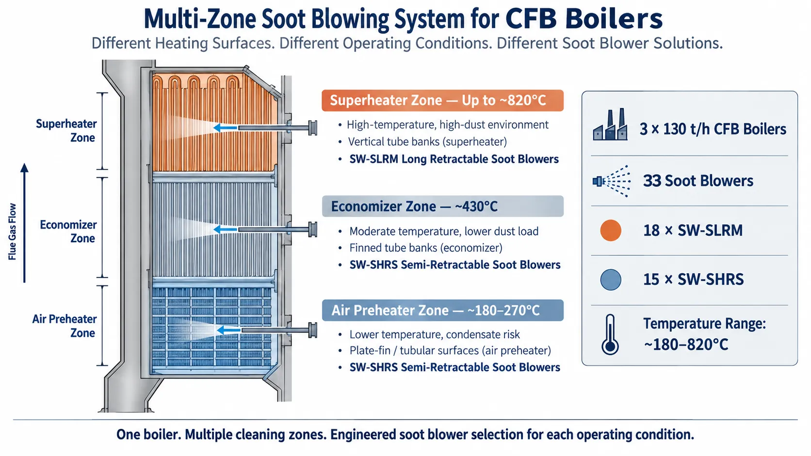
A boiler does not have one single soot blowing condition.
Flue-gas temperature, deposit characteristics, heating-surface geometry and available installation space can vary significantly from the superheater to the economizer and air preheater.
For this reason, an effective boiler cleaning system should not simply apply the same soot blower configuration at every elevation.
In this project, SHEENWAY engineered and supplied a multi-zone steam soot blowing system for three 130 t/h circulating fluidized bed boilers at an industrial facility in eastern China.
Each boiler was equipped with a combination of long retractable and semi-retractable soot blowers selected according to the operating conditions of different heating-surface zones.
Across the three boilers, the complete system incorporated:
18 SW-SLRM Long Retractable Soot Blowers
15 SW-SHRS Semi-Retractable Soot Blowers
for a total of:
33 steam soot blowers.
The system covered flue-gas temperature zones ranging from approximately 180°C to 820°C.
Project Overview
Each 130 t/h CFB boiler was equipped with:
- 6 SW-SLRM Long Retractable Soot Blowers
- 5 SW-SHRS Semi-Retractable Soot Blowers
The long retractable soot blowers were primarily arranged around the superheater sections, while the semi-retractable units served the economizer and air-preheater zones.
Across all three boilers, this resulted in:
- 18 long retractable soot blowers
- 15 semi-retractable soot blowers
- 33 soot blowers in total
The project-specific stroke was approximately:
3.7 m for the SW-SLRM units
and:
2.65 m for the SW-SHRS units
Both configurations were designed for approximately 360° blowing coverage and an effective cleaning radius of about 2 meters.
The project also included soot blower control cabinets, system engineering, boiler-interface components, electrical interfaces, P&ID and I/O documentation, DCS coordination, installation guidance, commissioning and technical support.
The Engineering Challenge: One Boiler, Multiple Cleaning Environments
A key characteristic of this project was the wide variation in operating conditions across the boiler.
The specified heating-surface zones included several superheater, economizer and air-preheater sections.
Representative flue-gas temperatures ranged from approximately:
- 820°C in the highest-temperature superheater region
- 570°C in a lower-temperature superheater section
- 430°C around the economizer
- 270°C
- 226°C
- down to approximately 180°C in air-preheater areas
This created a temperature span of more than 600°C across the soot blowing system.
The engineering question was therefore not simply:
“How many soot blowers does the boiler need?”
The more important question was:
“Which soot blower configuration is appropriate for each heating-surface zone?”
Long Retractable Soot Blowers for High-Temperature Superheater Zones
The higher-temperature superheater sections were equipped with SW-SLRM Long Retractable Soot Blowers.
The SW-SLRM design allows the lance tube to rotate while travelling into the boiler and then retract from the gas path after the cleaning cycle.
This operating principle is particularly suitable for higher-temperature regions because the lance is not permanently exposed to the hottest flue-gas environment.
The project-specific stroke of approximately 3.7 m was well within the operating range of the SW-SLRM series, whose current standard configuration supports strokes up to 7.60 m.
During each blowing cycle, the rotating steam jets provide the required cleaning coverage across the targeted superheater surfaces.
The soot blower configuration was selected with consideration for:
- Local flue-gas temperature
- Heating-surface geometry
- Required cleaning radius
- Lance travel
- Steam conditions
- Mechanical stability
- Boiler-tube protection
Semi-Retractable Soot Blowers for Economizer and Air-Preheater Sections
The lower-temperature sections of the boiler required a different approach.
For the economizer and air-preheater areas, the project utilized SW-SHRS Semi-Retractable Soot Blowers.
In a semi-retractable soot blower, part of the lance remains inside the boiler while several nozzle groups positioned along the lance clean different areas during the travel cycle.
This allows the effective cleaning zone to extend beyond the mechanical stroke of the soot blower.
The current SW-SHRS design is particularly suited to boiler regions such as economizers and tubular air preheaters where flue-gas temperatures are generally below approximately 600°C and where a full long-retractable installation may require unnecessary platform space.
This matched the actual project conditions particularly well.
The semi-retractable units were installed in zones with specified temperatures ranging from approximately 180°C to430°C.
Matching Soot Blower Type to Heating-Surface Conditions
The combination of SW-SLRM and SW-SHRS equipment illustrates an important principle of soot blowing engineering:
different boiler zones should be treated according to their actual operating conditions.
The higher-temperature superheater areas favored a fully retractable lance arrangement.
The lower-temperature economizer and air-preheater areas allowed part of the lance to remain within the gas path, making the semi-retractable configuration practical while reducing the required installation footprint.
Instead of standardizing every installation around one machine type, the system used two complementary soot blower configurations to achieve the required cleaning coverage.
This improves the overall balance between:
- Cleaning performance
- Temperature suitability
- Mechanical arrangement
- Platform-space requirements
- Equipment maintainability
Steam Conditions and Blowing-Medium Management
The project provided a site steam source of approximately:
2.8 MPa absolute pressure
at approximately:
285°C
The final operating conditions at each soot blower were subject to detailed engineering according to the required cleaning performance and equipment configuration.
Steam soot blowing performance depends on more than the pressure available at the main steam header.
The system must also consider:
- Pressure loss through piping and valves
- Condensate drainage
- Valve regulation
- Soot blower flow requirements
- Nozzle configuration
- Heating-surface cleaning requirements
The project therefore treated steam supply and soot blower operation as parts of one coordinated system.
Reliable Valve and Lance Protection
The soot blower valve arrangement was designed to provide reliable shutoff and appropriate pressure regulation during operation.
When the soot blower was not operating, an air-introduction arrangement could be used to help protect the valve and lance assembly.
This type of protection is particularly useful where temperature changes and residual steam conditions may otherwise leave moisture inside the equipment after a blowing cycle.
Proper valve closure, condensate control and internal component protection all contribute to long-term equipment reliability.
Mechanical Reliability Across 33 Units
A system containing 33 soot blowers places different demands on reliability than a small installation.
Each individual unit must repeatedly complete a coordinated sequence:
forward travel → rotation and blowing → reverse travel → return to standby
with consistent position feedback.
The project requirements therefore emphasized:
- Smooth carriage movement
- Stable lance rotation
- Accurate travel limits
- Reliable gearbox sealing
- Proper lubrication
- Lance alignment
- Electrical protection
- Maintainable component arrangement
When dozens of soot blowers operate across three boilers, consistent mechanical performance becomes a system-level requirement.
Integration with Plant Controls
The soot blowing system was designed to interface with the plant control architecture.
The project included soot blower control cabinets, sequence-control documentation, P&ID information and I/O lists, together with engineering coordination for DCS integration.
The control system allowed operators to monitor soot blower status and coordinate cleaning sequences rather than operating the equipment as isolated machines.
For a three-boiler installation, centralized control provides practical advantages in:
- Operating-sequence management
- Equipment-status monitoring
- Fault identification
- Maintenance planning
- Coordination between boiler cleaning zones
This transforms the soot blowers from individual pieces of mechanical equipment into a coordinated boiler-cleaning system.
A Humid Coastal Operating Environment
The project documentation also defined the external site environment in detail.
The industrial site is located in a humid coastal region of eastern China.
Design data included approximately:
- 81% annual average relative humidity
- 1,413 mm annual average precipitation
- maximum recorded wind speeds of approximately 40 m/s
Although the soot blowers themselves operate primarily within the boiler structure, the surrounding industrial environment still affects electrical enclosures, motors, exposed mechanical components and long-term corrosion protection.
The project therefore required appropriate environmental protection for electrical and mechanical equipment.
The site environment was considered together with the internal boiler conditions rather than as a separate issue.
Why This Project Matters
This project demonstrates an important capability that is easy to overlook in soot blower selection.
The objective was not to install the largest possible number of identical soot blowers.
It was to configure the cleaning system according to the actual boiler.
Across three 130 t/h circulating fluidized bed boilers, the system combined:
33 soot blowers
18 SW-SLRM long retractable units
15 SW-SHRS semi-retractable units
3.7 m and 2.65 m project strokes
superheater, economizer and air-preheater coverage
approximately 180–820°C operating zones
centralized control and DCS coordination
The technical value lies in selecting the appropriate soot blower configuration for each location.
A high-temperature superheater does not present the same engineering conditions as a low-temperature air preheater.
A compact economizer installation does not necessarily require the same equipment footprint as a superheater cleaning position.
For SHEENWAY, soot blower engineering begins by understanding these differences.
The right soot blower is not simply selected for the boiler — it is selected for the specific location inside the boiler.
SHEENWAY Multi-Zone Boiler Cleaning Solutions
SHEENWAY provides integrated soot blowing solutions for circulating fluidized bed boilers and other industrial boiler applications.
Our engineering capabilities include:
- SW-SLRM Long Retractable Soot Blowers
- SW-SHRS Semi-Retractable Soot Blowers
- Furnace soot blowers
- Fixed rotary soot blowers
- Air-preheater soot blowers
- Steam and drainage system engineering
- Boiler-interface design
- Soot blower control systems
- DCS integration
- Replacement parts
- Installation and commissioning support
For multi-zone boiler applications, SHEENWAY evaluates flue-gas temperature, heating-surface geometry, ash conditions, steam parameters, platform space and control requirements before determining the final combination of soot blower types.
Planning a soot blowing system for a CFB or industrial boiler? Contact SHEENWAY to discuss the operating conditions of each boiler cleaning zone.
More from Sheenway
Continue Reading
Retractable Boiler Temperature Probe: Why It Matters During Boiler Startup
During boiler startup, furnace exit gas temperatures can rise before sufficient steam cooling is established in certain heating surfaces. A retractable boiler temperature probe positions a thermocouple in the gas path to provide temperature information for operating decisions. This guide explains the working principle, startup applications, measurement limitations and selection requirements of the SHEENWAY SW-MTPS.
Read articleRake-Type Soot Blower Design for SCR: Nozzle Layout, Travel and Support
Rake-type soot blowers use non-rotating, axially moving cleaning assemblies to direct steam or compressed air toward SCR catalysts and other structured surfaces. This guide explains nozzle layout, travel, support and guide arrangements, cleaning-medium conditions and the engineering checks required before selecting or replacing a rake-type soot blower.
Read articleMulti-Medium Retractable Soot Blowers: When Steam Alone Is Not Enough
Steam soot blowing is effective for many boiler cleaning applications, but certain gypsum, salt and strongly bonded deposits may require additional cleaning methods. This guide explains how multi-medium retractable soot blowers combine different cleaning options, when water washing may be considered, and how engineers select an appropriate solution for gas-gas heaters and air preheaters.
Read article