
Air Preheater Fouling: Why Pressure Drop and Flue-Gas Temperature Rise — and How Soot Blowing Helps
Air-preheater fouling can restrict flue-gas passages, reduce heat-transfer performance and contribute to rising system resistance and flue-gas temperature. This article explains why deposits develop, how rotary air-preheater soot blowing works, and which engineering parameters affect cleaning coverage.
Air Preheater Fouling: Why Pressure Drop and Flue-Gas Temperature Rise — and How Soot Blowing Helps
An air preheater is one of the final major heat-recovery devices in many boiler flue-gas systems.
Its function is straightforward: recover heat from the outgoing flue gas and use that energy to warm the incoming combustion air.
The operating benefit is important. Heat that would otherwise leave through the stack is returned to the combustion process.
But this position in the boiler also creates a persistent operating problem.
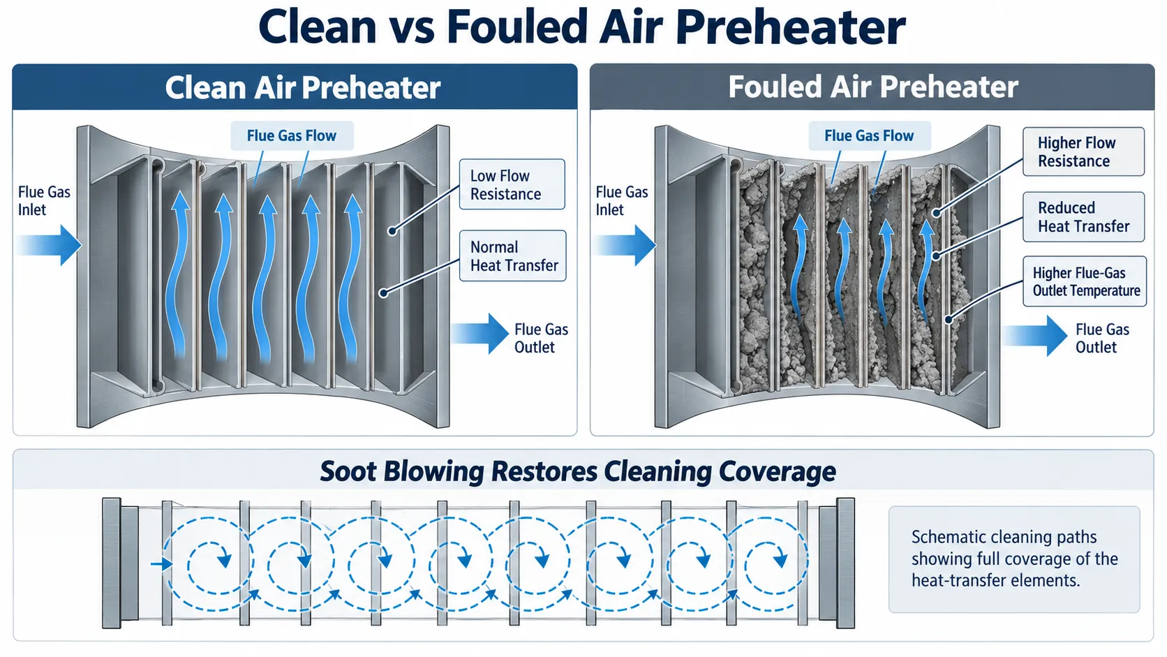
By the time the flue gas reaches the air preheater, it can still carry significant quantities of fly ash and other particulate or chemical deposits. Because the heat-transfer elements contain relatively narrow gas passages, deposits can gradually accumulate inside the structure.
As fouling develops, two symptoms frequently become increasingly important:
higher gas-side resistance and deteriorating heat-transfer performance.
These changes can ultimately be reflected in rising pressure loss and higher flue-gas temperature leaving the air preheater.
SHEENWAY's boiler-cleaning material specifically identifies air-preheater fouling as a cause of blockage, increasing resistance and rising exhaust-gas temperature.
Understanding why this happens is essential before deciding how the air preheater should be cleaned.
Why Is the Air Preheater Particularly Sensitive to Fouling?
The problem begins with geometry.
Air-preheater heat-transfer elements are designed to provide a large surface area within a relatively compact space.
This is beneficial for heat recovery, but it also creates many narrow passages through which the flue gas must travel.
Particles carried by the gas can enter these passages and deposit on the heat-transfer surfaces.
At first, a relatively thin deposit may not appear serious.
But as deposits accumulate, the effective flow area becomes smaller.
A useful way to think about the process is:
Clean passage → initial deposition → reduced free area → higher resistance → further operating deterioration
Because the air preheater processes a very large volume of flue gas continuously, even gradual changes in passage condition can become operationally significant.
Fouling Increases Gas-Side Resistance
When deposits accumulate between heat-transfer elements, the available flow area decreases.
The same flue-gas flow must then pass through a more restricted path.
From an operating perspective, this means increasing resistance through the air-preheater section.
The effect is not only a question of whether the air preheater is completely blocked.
Long before complete blockage occurs, partial fouling can already change the gas-flow characteristics of the equipment.
This is why pressure-drop trends are useful operating indicators.
A gradual increase in resistance can be a sign that deposit accumulation is becoming more severe, especially when the change cannot be explained by boiler load or other operating conditions.
Cleaning should therefore be considered as part of maintaining the gas path—not simply as a cosmetic removal of visible ash.
Fouling Also Reduces Effective Heat Transfer
The air preheater exists to transfer energy from hot flue gas to combustion air.
Deposits interfere with this process in two ways.
First, ash accumulating on the heat-transfer surface introduces an additional layer between the flue gas and the heat-transfer element.
Second, severe accumulation can interfere with gas distribution through the heat-transfer matrix.
The result is that the air preheater may recover less useful heat from the flue gas than it would under cleaner conditions.
If less heat is extracted before the gas leaves the air preheater, the downstream flue-gas temperature can increase.
This is one reason rising exhaust-gas temperature and increasing air-preheater resistance should be considered together rather than as completely independent problems.
They may both reflect deterioration of the heat-transfer section.
Not All Air-Preheater Deposits Are the Same
It is also important not to treat every air-preheater deposit simply as “fly ash.”
Deposit characteristics can vary depending on:
- fuel composition,
- ash characteristics,
- flue-gas chemistry,
- operating temperature,
- upstream emission-control equipment,
- and local temperature distribution within the air preheater.
SHEENWAY's boiler-cleaning material notes that the lower-temperature section of an air preheater can be affected by acidic corrosion and deposition, creating both blockage and material-degradation concerns.
In other applications, particularly around downstream gas-treatment and heat-exchange systems, salt deposits and scale can also become relevant.
This distinction matters because a loose dry-ash deposit and a more strongly bonded chemical deposit may not respond to the same cleaning strategy.
Cleaning technology therefore needs to match the deposit rather than simply the equipment name.
How Does an Air Preheater Soot Blower Work?
For a rotary air preheater, the cleaning geometry is different from that of a stationary boiler tube bank.
SHEENWAY's SW-SAHS Air Preheater Soot Blower uses steam or compressed air as the blowing medium and is specifically intended for cleaning the heating surfaces of a rotary air preheater.
An important point is that the two major movements come from different components.
During operation:
the soot-blower lance moves linearly, while the rotary air preheater itself continues rotating.
The lance therefore does not need to reproduce the entire cleaning pattern through its own rotation.
Instead, the movement of the lance combines with the rotation of the air preheater.
This creates a series of spiral cleaning trajectories across the heat-transfer surface.
In the SW-SAHS design, the resulting nozzle paths are described as several Archimedean spirals. Multiple nozzles work together to progressively cover the air-preheater heating surface.
This is a good example of an important soot-blower design principle:
the cleaning motion must match the motion and geometry of the equipment being cleaned.
Why Nozzle Arrangement Matters
An air-preheater soot blower is not simply a long pipe that releases steam.
The diameter, number and spacing of the nozzle openings must be matched to the particular air-preheater arrangement.
SHEENWAY's SW-SAHS documentation specifically states that the lance configuration, nozzle diameter and nozzle spacing are designed according to the air preheater and installation requirements.
This matters because the cleaning jets need to provide adequate coverage while the rotor and lance are moving relative to one another.
If nozzle spacing is poorly matched to the rotor geometry, some areas may receive excessive overlap while others may receive insufficient cleaning.
The objective is therefore not simply to maximize the number of nozzles.
It is to create an effective cleaning pattern across the target surface.
Nozzle Distance Changes Cleaning Coverage
The distance between the nozzle and the air-preheater surface is another significant parameter.
A cleaning jet does not maintain exactly the same cross-section as it travels away from the nozzle.
It has a certain diffusion angle, meaning that the effective coverage becomes wider with increasing distance.
The SW-SAHS documentation provides a useful example.
When the nozzle is approximately:
200 mm from the air-preheater sector plate, the coverage width is about 64 mm.
When the distance increases to approximately:
300 mm, the coverage width can reach about 95 mm.
This demonstrates why installation distance cannot be treated as a minor dimensional detail.
Changing the distance changes the area covered by the jet.
At the same time, wider coverage should not automatically be interpreted as stronger cleaning.
The distribution of cleaning energy also changes as the jet propagates.
Nozzle distance, jet coverage and cleaning intensity therefore need to be evaluated together.
Typical SW-SAHS Engineering Parameters
For reference, the current SHEENWAY SW-SAHS documentation lists the following general parameters:
| Parameter | SW-SAHS Reference |
|---|---|
| Application | Rotary air preheater |
| Blowing medium | Steam or compressed air |
| Blowing pressure | Approx. 1.5 MPa |
| Effective blowing radius | Approx. 2 m |
| Stroke | Determined according to project requirements |
| Lance movement speed | Determined according to project requirements |
| Nozzle quantity and diameter | Determined according to project requirements |
| Drive motor | 0.18 kW, approx. 1370 r/min |
These values should not be interpreted as one fixed configuration for every air preheater.
The documentation specifically leaves stroke, movement speed and nozzle configuration dependent on the project because different air-preheater dimensions and installation arrangements require different cleaning coverage.
Why Continuous Soot Blowing Is Not Necessarily the Answer
If fouling is harmful, it may seem logical to operate the soot blower as frequently as possible.
In practice, soot blowing should be controlled rather than treated as a continuously active process.
The broader SHEENWAY boiler-cleaning material emphasizes that soot-blower frequency, sequence and operating method should be selected according to boiler load, fuel characteristics and the actual fouling condition.
This principle also applies to air-preheater cleaning.
The objective is not to maximize the number of cleaning cycles.
The objective is to maintain acceptable heat-transfer and gas-flow conditions with an appropriate cleaning strategy.
Useful operating indicators may include trends in:
- air-preheater pressure drop,
- flue-gas outlet temperature,
- boiler load,
- fuel condition,
- and observed deposit severity.
A trend-based approach is usually more meaningful than assuming that one fixed cleaning frequency is optimal under every operating condition.
What If Steam Soot Blowing Is Not Enough?
Some deposits are more difficult than ordinary loose fly ash.
Where chemical salts, scale or more strongly bonded deposits are present, a different or supplementary cleaning method may be necessary.
SHEENWAY's product range therefore also includes the SW-SMRS Multi-Medium Retractable Soot Blower, designed for applications involving deposits and scale on equipment such as GGH units and certain air-preheater applications downstream of emission-control systems.
The system can use:
- superheated steam,
- compressed air,
- low-pressure water,
- or high-pressure water,
depending on the project and cleaning requirement.
This illustrates an important engineering point:
A cleaning system should be selected according to the nature of the deposit, not simply according to the name of the heat exchanger.
Dry particulate fouling and strongly bonded scale may require different strategies.
What Information Is Needed When Selecting or Retrofitting an Air Preheater Soot Blower?
For a new installation or replacement project, knowing only the existing soot-blower model is usually not enough.
Important engineering information includes:
Air-preheater type and dimensions
The rotor diameter, heating-element arrangement and available installation space determine the required coverage.
Required stroke
The lance must travel far enough to cover the intended cleaning area.
Nozzle-to-surface distance
This influences both jet coverage and cleaning-energy distribution.
Existing deposit characteristics
Loose ash, sticky deposits and scale may require different cleaning strategies.
Available steam or compressed-air conditions
Pressure and available flow influence the practical nozzle design.
Rotor operating conditions
Because cleaning coverage is created by the interaction between lance movement and rotor rotation, operating conditions matter.
Existing wall connections and structural interfaces
Retrofit equipment must be mechanically compatible with the existing boiler and air-preheater arrangement.
Control requirements
Travel limits, cleaning sequence and interaction with the plant control system should also be confirmed.
For retrofit projects, the goal is therefore not simply to reproduce the physical dimensions of an existing soot blower.
The new cleaning system should reproduce—or improve—the required cleaning coverage under the actual operating conditions.
Air Preheater Fouling Should Be Treated as a System Problem
When air-preheater performance deteriorates, simply replacing a soot blower may not always solve the underlying problem.
It is useful to distinguish among several questions:
Is cleaning coverage insufficient?
Has deposit chemistry changed?
Has fuel quality changed?
Are nozzle distance or nozzle arrangement appropriate?
Are steam pressure and flow still sufficient?
Has the cleaning sequence changed?
Is the deposit primarily loose ash, or has it developed into a more strongly bonded layer?
These questions help separate an equipment failure from a cleaning-strategy problem.
That distinction is important because the correct solution may involve maintenance, parameter adjustment, nozzle redesign, operating-sequence changes or, in some cases, a different cleaning technology.
Conclusion
Air-preheater fouling affects much more than surface cleanliness.
As deposits accumulate within the heat-transfer matrix, they can restrict the flue-gas path, increase resistance and reduce effective heat recovery.
The resulting operating symptoms may include increasing pressure loss and higher flue-gas outlet temperature.
For rotary air preheaters, effective soot blowing depends on coordinated cleaning geometry.
In the SHEENWAY SW-SAHS system, linear lance movement works together with air-preheater rotation to produce spiral cleaning trajectories across the heating surface. Nozzle spacing, diameter, installation distance, blowing pressure and stroke all influence the final cleaning coverage.
For this reason, an air-preheater soot blower should not be selected as an isolated machine.
It should be engineered as part of the air-preheater cleaning system, based on equipment geometry, deposit characteristics, available cleaning medium and actual operating conditions.
More from Sheenway
Continue Reading
Retractable Boiler Temperature Probe: Why It Matters During Boiler Startup
During boiler startup, furnace exit gas temperatures can rise before sufficient steam cooling is established in certain heating surfaces. A retractable boiler temperature probe positions a thermocouple in the gas path to provide temperature information for operating decisions. This guide explains the working principle, startup applications, measurement limitations and selection requirements of the SHEENWAY SW-MTPS.
Read articleRake-Type Soot Blower Design for SCR: Nozzle Layout, Travel and Support
Rake-type soot blowers use non-rotating, axially moving cleaning assemblies to direct steam or compressed air toward SCR catalysts and other structured surfaces. This guide explains nozzle layout, travel, support and guide arrangements, cleaning-medium conditions and the engineering checks required before selecting or replacing a rake-type soot blower.
Read articleMulti-Medium Retractable Soot Blowers: When Steam Alone Is Not Enough
Steam soot blowing is effective for many boiler cleaning applications, but certain gypsum, salt and strongly bonded deposits may require additional cleaning methods. This guide explains how multi-medium retractable soot blowers combine different cleaning options, when water washing may be considered, and how engineers select an appropriate solution for gas-gas heaters and air preheaters.
Read article